Contents
Overview
This section contains notes about the disassembly of the VP415 including details such as screw dimensions and head types (all screw lengths are not including the head). This section will be completed as players are disassembled, so please excuse any missing information. Note: M3 is a standard M3 thread. 3M is a self tapping screw of the same width.
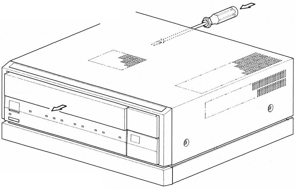
Ejecting the front-loader tray
Manual ejection of the front-loader tray is performed by pushing a wide flat-bladed screw driver through the hole in the back panel.
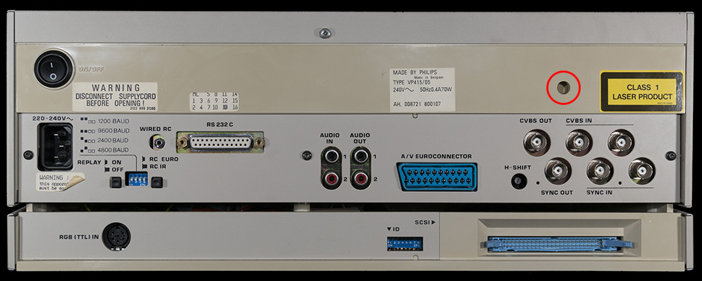
The correct hole is shown in the following picture (marked in red):
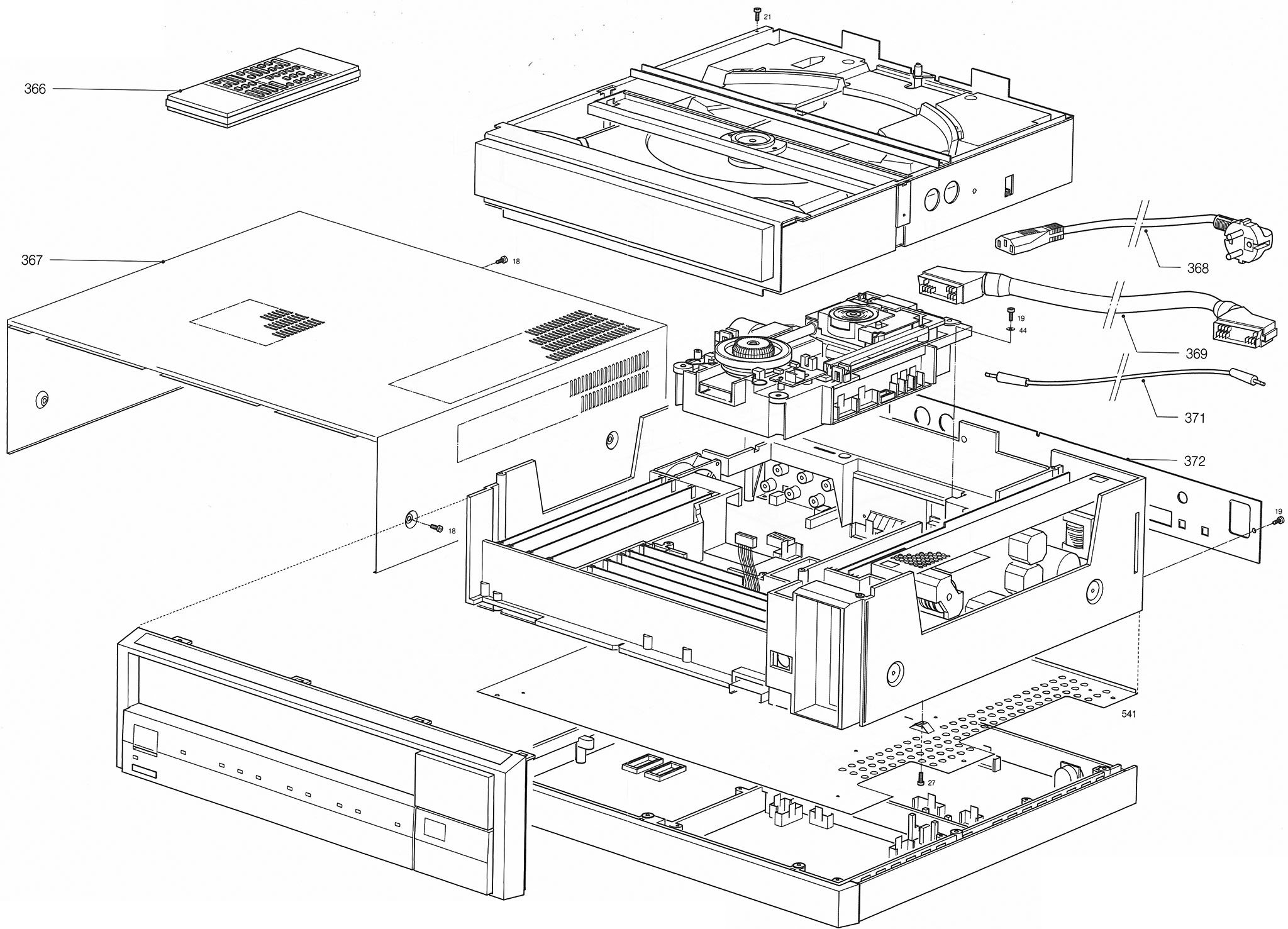
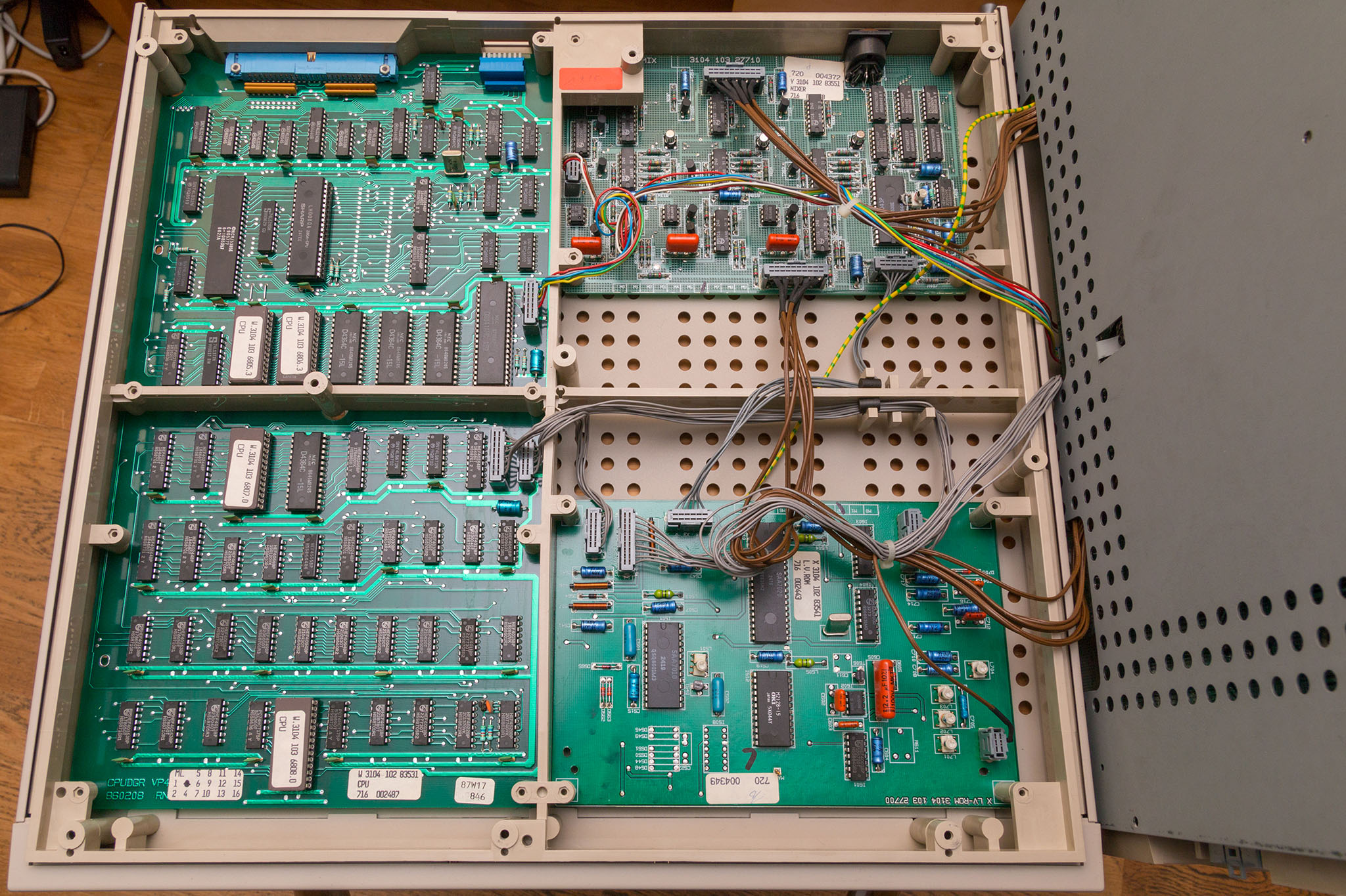
Modules
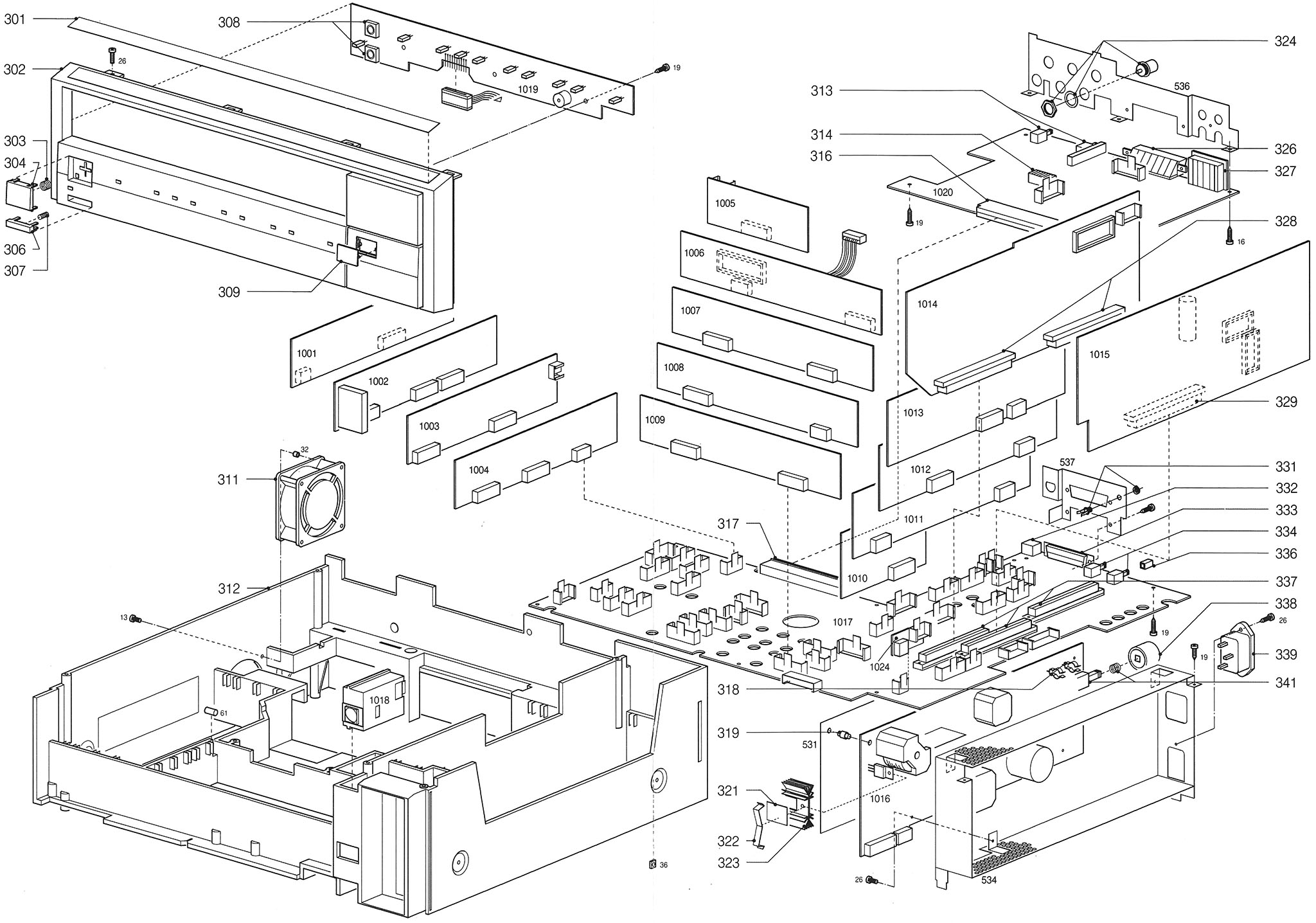
For details of the various modules and their purpose please see the Philips VP415 module guide.
Screws:
- DR13 - M3 x 7mm (T10) - fan
- DR16 - Part of the I/O module - removal not required for disassembly of the main assembly
- DR19 - 3M x 10mm (T10) (same all round the module carrier except the earth terminal which is silver 3M x 12mm with a washer (note this is 3M x 10mm on the VP410) and the screw holding in the RS323 module which is 3M x 6mm (at the back of the player). Note: The 2 screws marked 19 holding the power supply module are 3M x 12mm (T10)
- DR26 - See UC2* below
Note: There is also a 3M x 10mm (T10) in the front of the RS232 module (not shown in the service manual diagram).
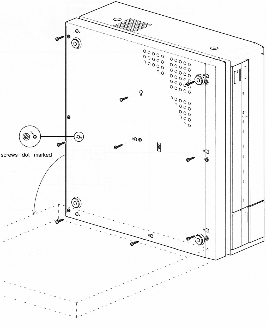
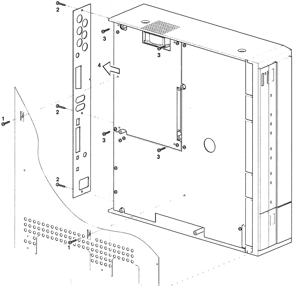
Cabinet
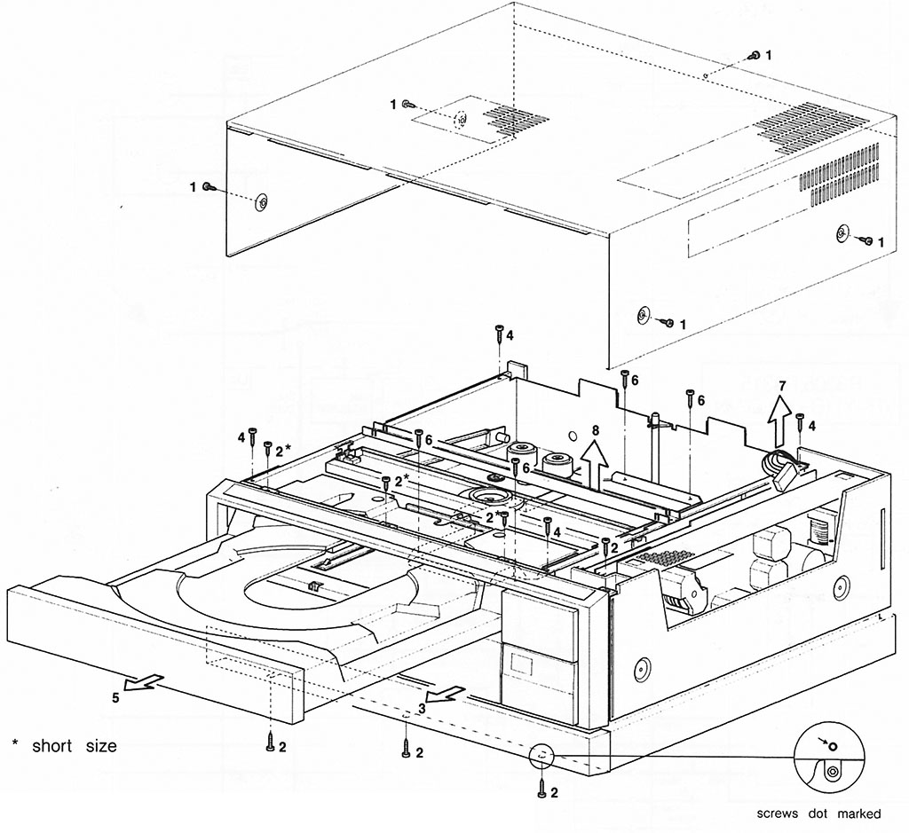
Screws:
- UC1 - M3 x 8mm (Philips head)
- UC2* - 3M x 6mm (T10)
- UC2 - 3M x 12mm (T10) Note: The screw marked '2' on the top-left of the front-panel is 3M x 10mm (T10)
- UC4 - 3M x 12mm (T10)
- UC6 - 3M x 12mm (T10)
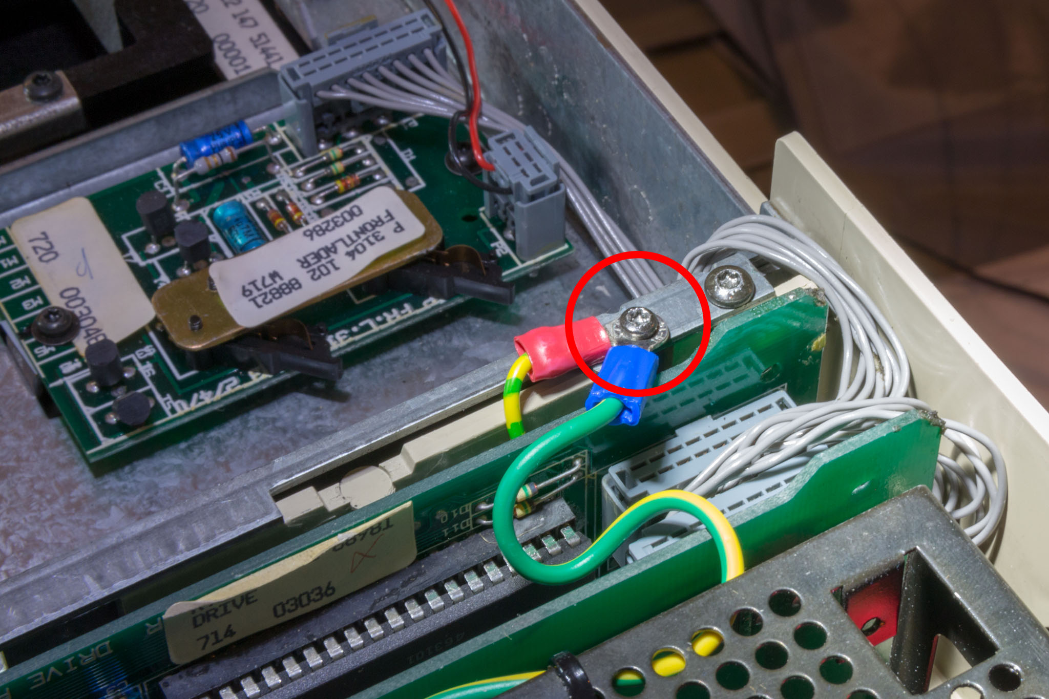
Service manual diagram does not show M2.5 x 5mm screw (T7) holding earthing connections onto the metal frame of the front-loader next to power supply module:
Screws:
- CB18 - (UC1) M3 x 8mm (Philips head)
- CB19 - 3M x 10mm (T10)
- CB21 -
- CB27 - 3M x 10mm (T10 Silver or black depending on the player)
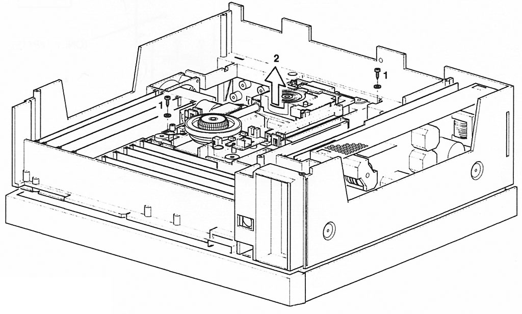
Sandwich
Screws:
- SW1 - 3M x 12mm (T10)
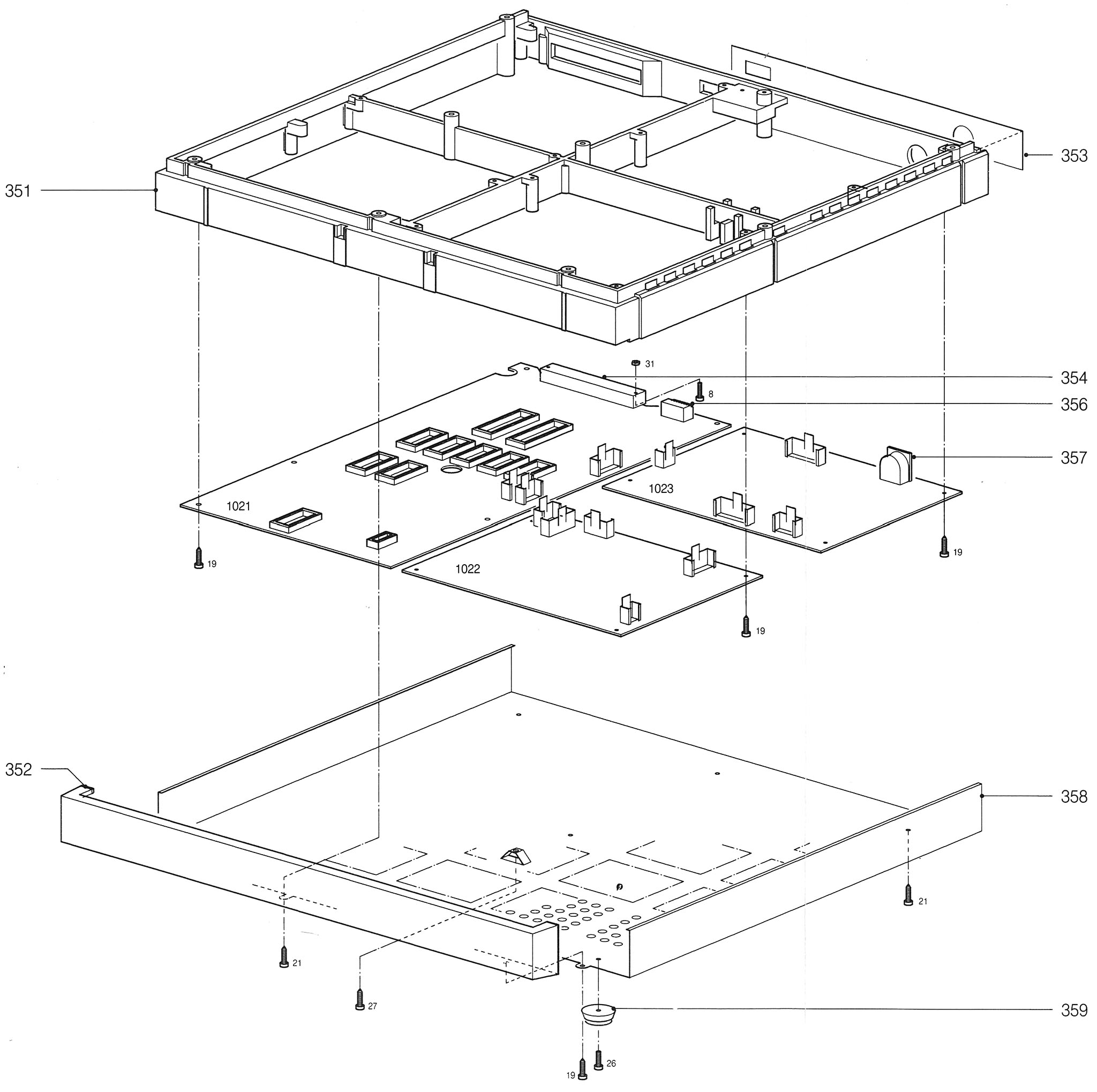
Screws:
- SN8 - M2 x 10mm (T7) with nut
- SN19 - 3M x 10mm (T10)
- SN21 - 3M x 10mm (T10) - 7 screws holding in the metal plate (6 around the outside and one in the centre)
- SN26 - 3M x 8mm (T10)
- SN27 - 3M x 10mm (T10) - Silver screw with washer (6mm M3 screw with washer on some players)
Note that, in order to remove the sandwich you must also remove SN27 to release the earth wire (as well as the appropriate module connectors). Refitting SN27 requires removal of the metal base plate in order to access the connector.
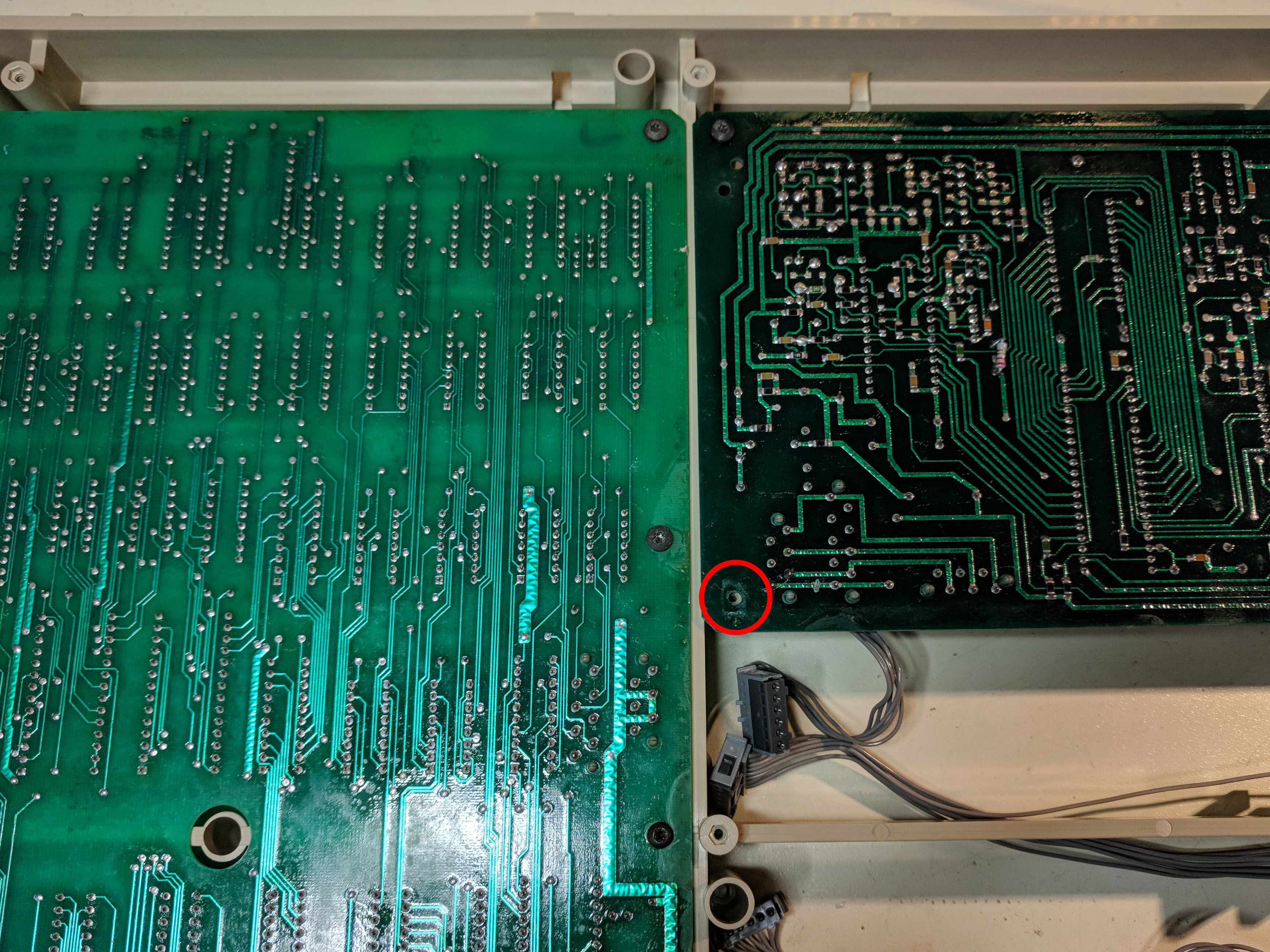
The following photo shows the sandwich removed from the upper-case (but not disconnected):
When replacing the boards into the sandwich be careful of the screw shown in the following picture. This is the only board mount screw which goes through the exterior metal case and should be left empty until the case is replaced:
Front-loader
Screws:
- FL1 -
- FL2 - M2 x 3mm (T7) (also used on 241 and not shown in service manual diagram). Screws holding 237 are M2 x 5mm (incorrectly shown in service manual)
- FL3 -
- FL6 - M2 x 6mm (T7)
- FL7 - M2 x 8mm (T7) silver
- FL12 - M2 x 6mm (T7) - with special brass nut (234)
- FL19 - 3M x 10mm (T10) holds in front-plate (3 screws)
- FL28 - 3M x 22mm (T10)
Note: Plastic part 236 is only fitted on older versions of the player.
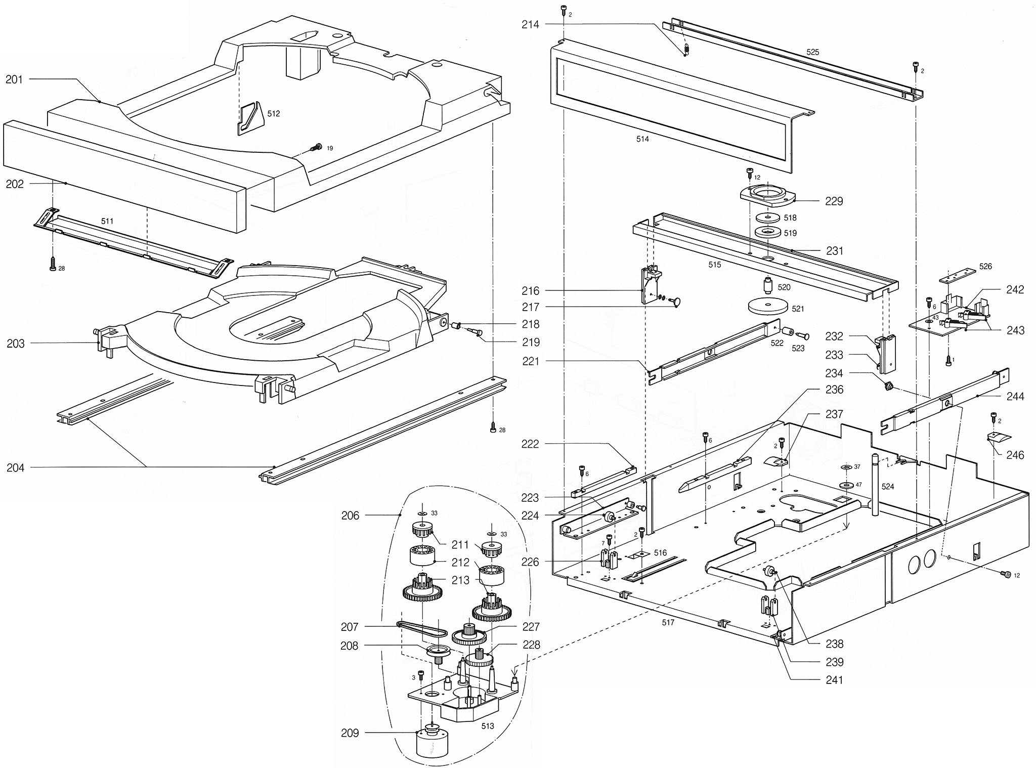
Note: 231 (the upper spindle support) is shown the wrong way around in the exploded diagram. It should be orientated so there is minimal gap between it and part 525.
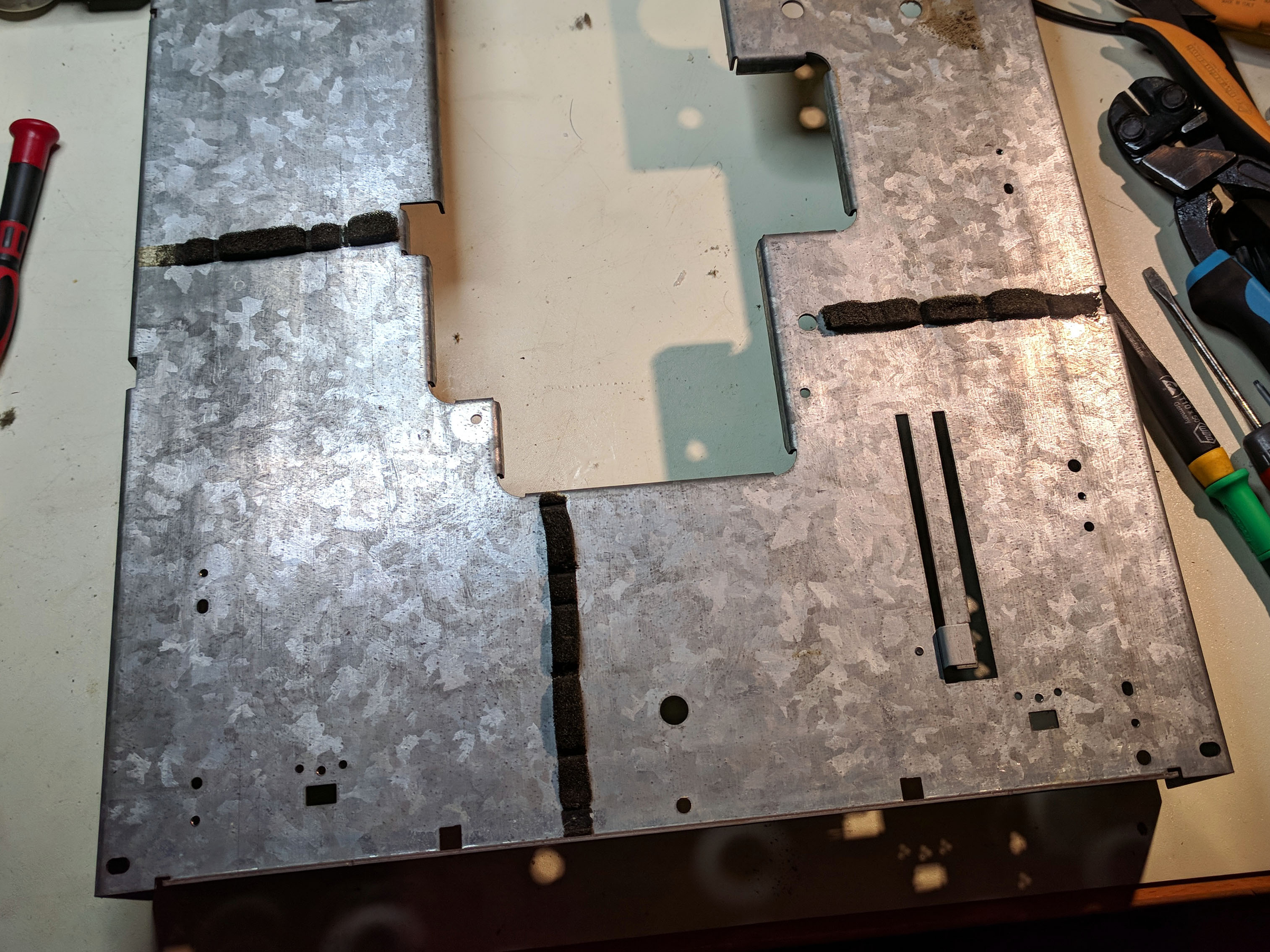
The front-loader has 3 strips of foam on the underside to protect the player's modules from vibration. The location of the foam strips are as shown in the following picture:
Analogue IO module (U)
Screws:
- MU1 - 3M x 10mm (T10) silver at back (ground) and 3M x 12mm (T10) centre
- MU2 - 3M x 10mm (T10) with 3M x 12mm next to the power connector
- MU3 - 3M x 10mm (T10)
Note: VP410 has 3 screws at the front 2x 3M x 10mm (T10) and 1x 3M x 12mm under IR module slot. All other screws in the VP410 base-plate are 3M x 12mm (T10).
Optical deck
Screws:
- OD1 - 3M x 10mm (T10)