Contents
13.5Mhz Clock generation calibration
This calibration sets the clock generator on the drop-out correction module to 13.5Mhz. Note: This is a partial calibration, please see the service manual for more details.
Setting up the oscilloscope
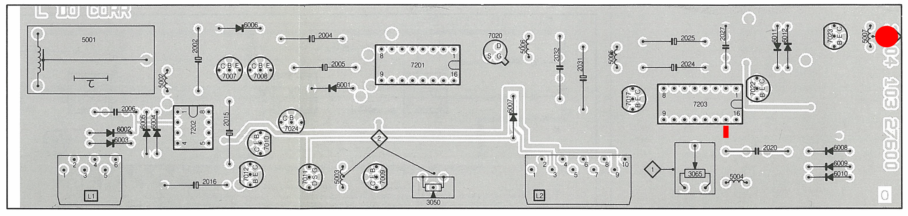
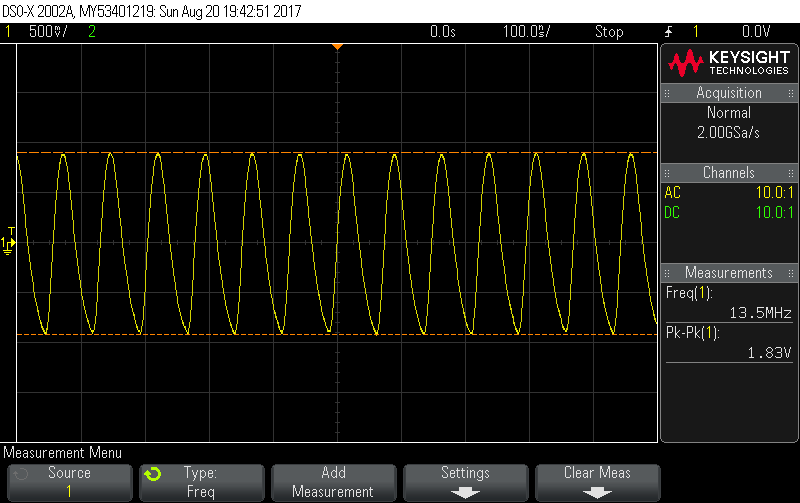
Connect the scope channel 1 to pin 15 of 7203 (TL8704P) and ground the probe on 10L2. Set up channel 1 to AC coupled, 500mV vertical divisions and 100ms horizontal divisions and measure frequency.
Adjustment points
Adjust coil 5007 until the clock generator outputs 13.5MHz to pin 15 of 7203 (anticlockwise increases clock speed) as shown in the following trace (note that it is not necessary to play a disc when performing this test):
Input to CCD delay calibration
TBA
MTF Calibration
TBA