Contents
Overview
The supply module (T) in the VP415 is a switched-mode power supply that provides the conversion between 240VAC and the 4 power supply levels required by the various other modules in the VP415 (+5V, -5V, +12V and -12V). Repair of old power supplies is generally not recommended as a modern supply will be safer, provide cleaner power and provide better protection to both the user and the electronics. Please note that replacement of this module involves wiring and components that will be handling mains electricity and should not be attempted unless you know what you are doing. If you are unsure, please find a qualified engineer and ask them to perform the modifications for you. Please note that the author does not guarantee accuracy and, as with any modification to the player you run the risk of inadvertently breaking your VP415. Please ensure that you use the correct ESD protection when performing any service work on the VP415 and take adequate safety measures when dealing with mains electricity.
Prerequisites
The primary components required for replacement of the supply module are shown in the following picture:
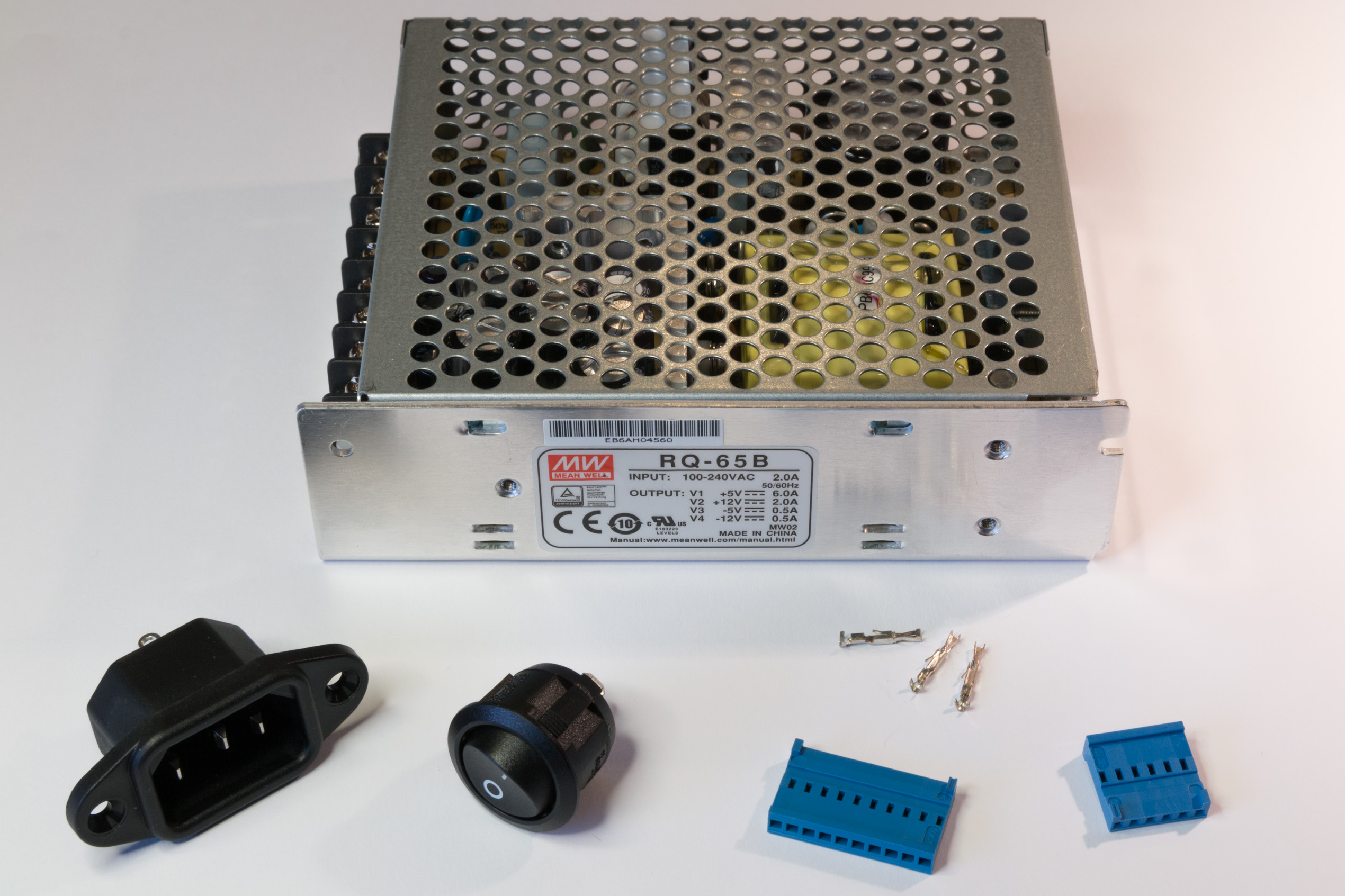
The parts are as follows:
- Mean well RQ-65B Switched Mode Power Supply module - Distrelec article number 169-05-919
- Schurter 6162.0046 C14 screw mounting plug - Distrelec article number 143-49-922
- Arcolectric single-pole 10A rocker switch (R13112AAAA) - Distrelec article number 300-13-205
- TE Connectivity 1x10 pole 2.54mm pitch cable socket housing (1-281838-0) - Distrelec article number 143-79-112
- TE Connectivity 1x6 pole 2.54mm pitch cable socket housing (281838-6) - Distrelec article number 143-79-095
- TE Connectivity crimp socket female (182734-2) - Distrelec article number 143-79-418 (x14)
You will also need hook-up wire (for the regulated side of the supply) and mains wire of the correct colour. In addition you will need shrink wrap tubing, spade connectors (for connecting the switch) and zip-ties. The required tools include wire cutters, wire strippers, a heat gun and the appropriate crimping tools.
The Mean Well power supply not only provides the required 4 voltage levels, it also features overload and short protection that will help to protect your VP415 during service, repair and general use.
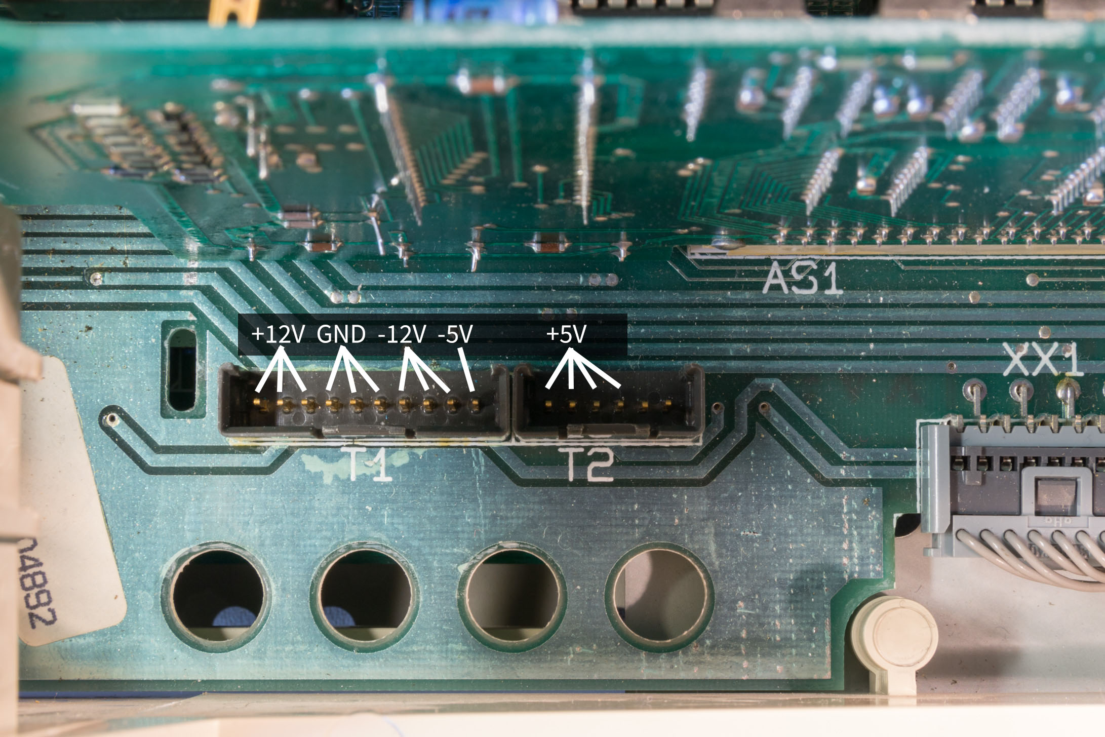
VP415 backplane pinout
The pinout of the two power connectors present on the VP415's backplane are as follows (note that the T1 power connector in the service manual schematic is numbered incorrectly; this picture is the correct pinout):
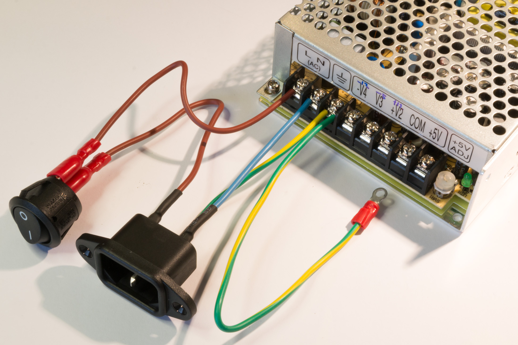
Mains power cabling
You will need to cut and tin the following lengths of mains power wires:
- 2 Brown (live) wires approximately 14cm long
- 2 Green/Yellow (earth) wire approximately 9cm and 19cm long
- 1 Blue (neutral) wire approximately 9cm long
Next connect the wires as shown in the following picture. The mains socket is soldered and shrink-wrapped, the switch and frame earth cables are crimped with spade/ring connectors:
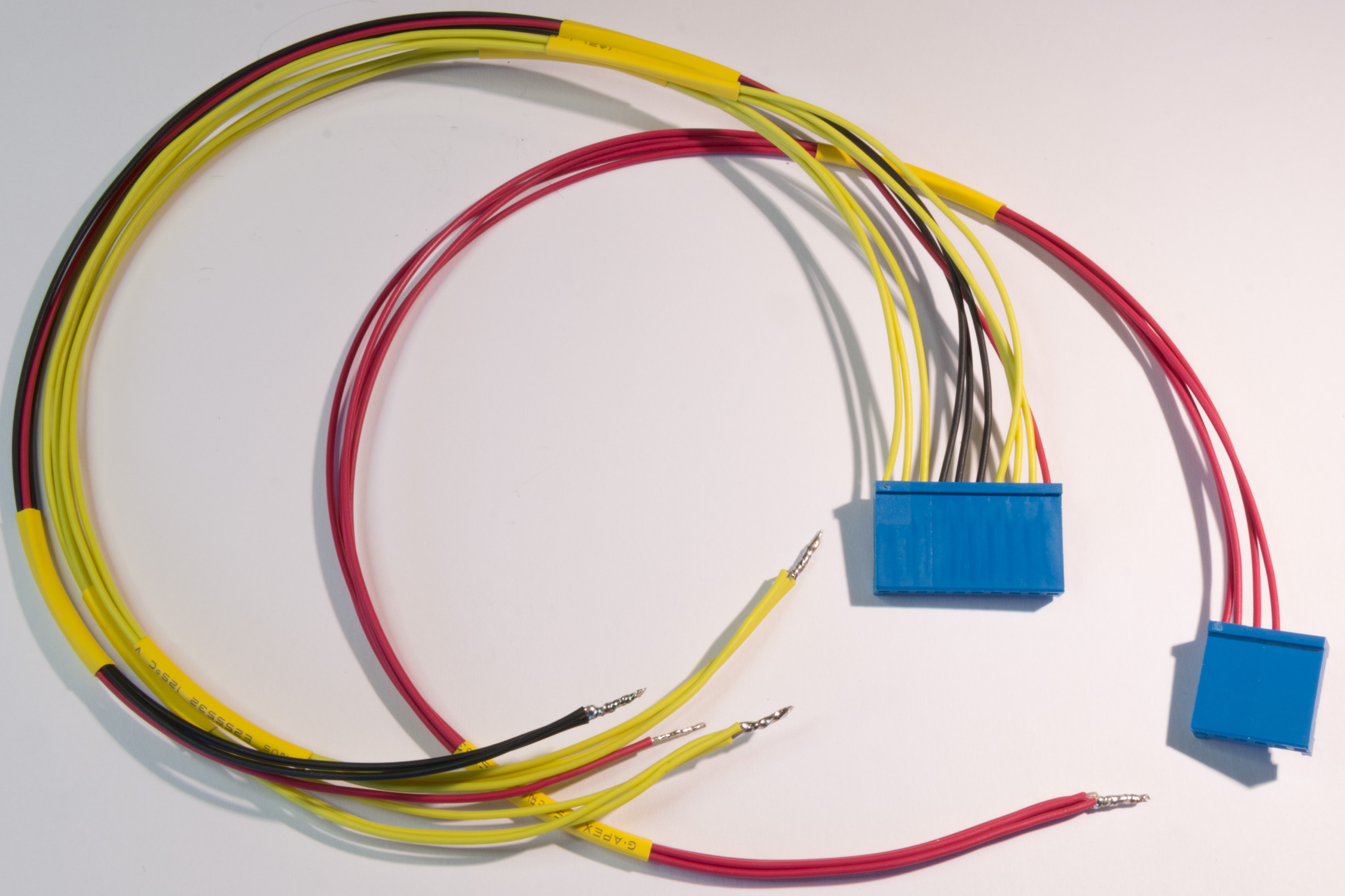
DC Power cabling
You will need the following lengths of cable:
- 6 Yellow cables approximately 35cm long (3 for +12V and 3 for -12V)
- 3 Black cables approximately 35cm long
- 5 Red cables approximately 35cm long (4 for +5V and 1 for -5Vs)
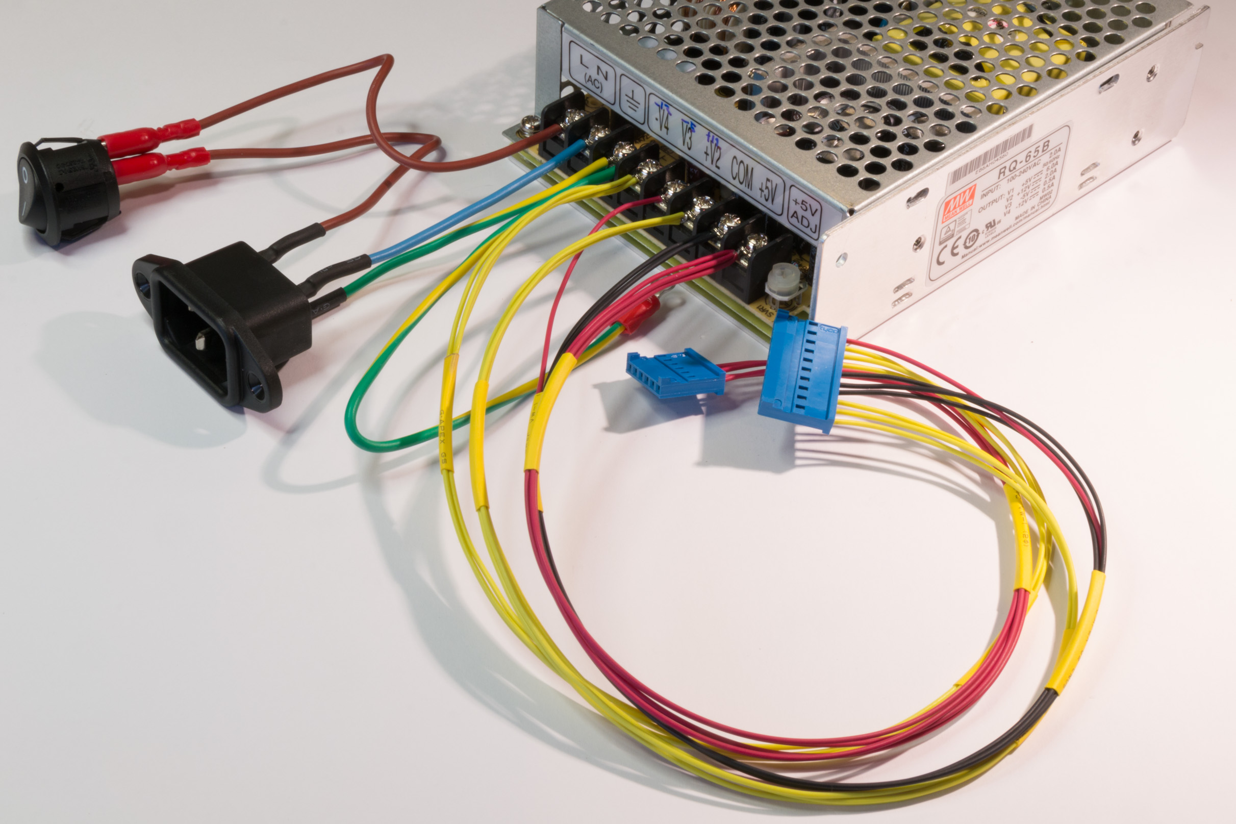
Strip the cable ends and crimp the female crimp sockets to one end of each wire. Insert the crimp connectors into the 10 and 6 pole connectors (as shown in the following picture). At the un-crimped end of the wired, group and twist them together and tin them with solder to make it easier to connect the wires to the screw terminals of the power supply (be careful to place the wires in the correct places):
Finally, connect the wires up to the power supply unit following the VP415 backplane pinout show in the pinout section of this article. The completed wiring should look like the following picture (check and double-check your work here; you really don't want this cabling to be the wrong way around!):
Mounting the power supply in the frame
The power supply can be mounted in the original frame (after the original supply board has been removed of course). The power supply is held in place by two flat-top screws in the top of the frame and two zip ties at the bottom of the frame. The switch should be disconnected before mounting in the player. It's advisable to add labelling to the power supply module too (just so you know how to connect it in the future should you need to make repairs to the VP415). After mounting in the frame, zip-tie all of the cabling to ensure it does not get tangled as the module is inserted into the player. The completed frame should look like the following picture:
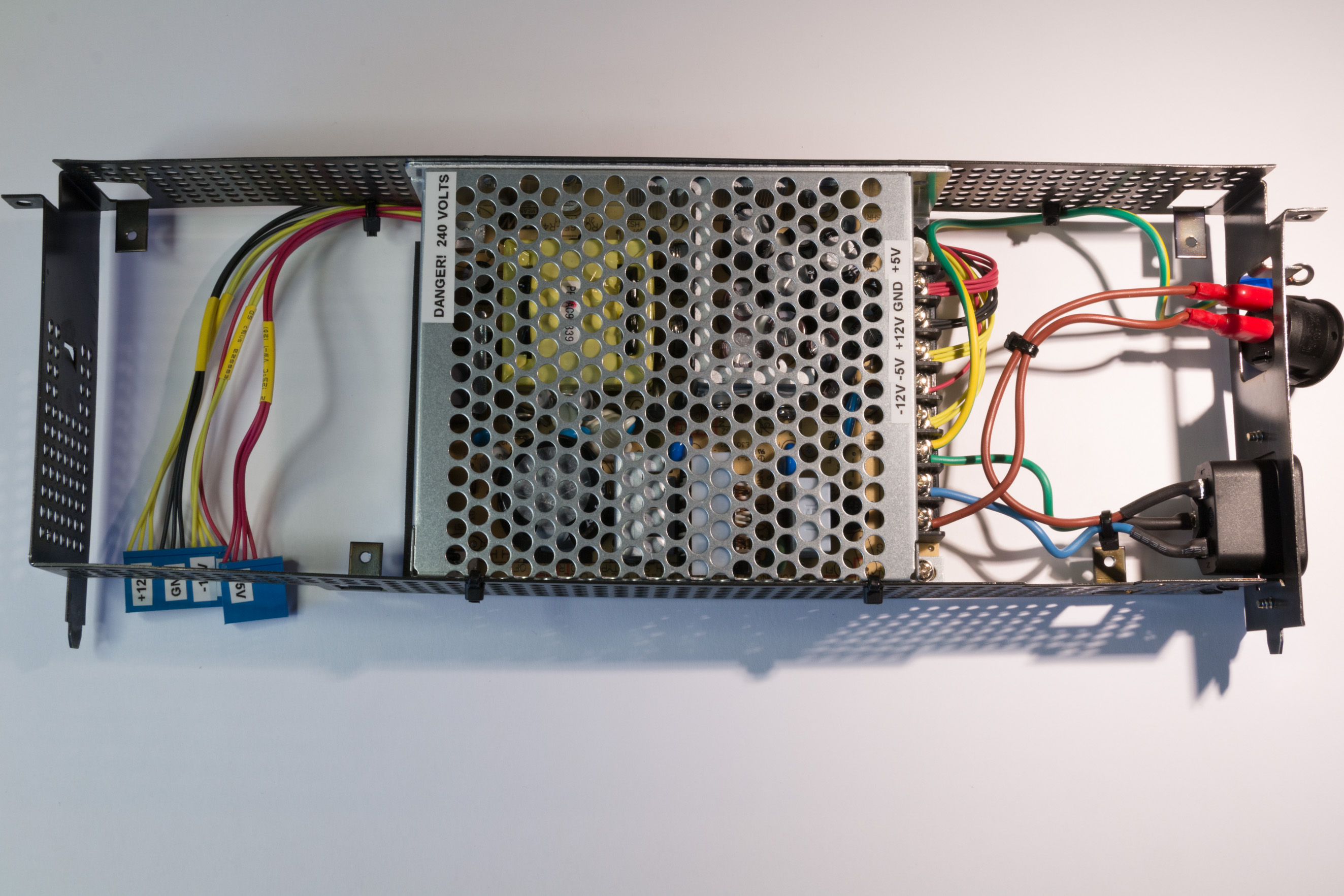
As the back of the Mean Well power supply is bare metal it should be covered with a non-conductive material (like plastic) to prevent any accidental shorting of nearby modules. For this I used a cut-up piece of a thin mouse-mat and some double-sided sticky foam to hold it in place.
Mounting the module into the VP415
With the exception of the power switch (see below) the module can be fitted into the VP415 as per the original module. Insert the frame into the player ensuring that the frame earth cable is routed correctly and none of the cables are tangled or pinched, then screw the frame into the player's frame using the two original screws. Next connect the 10 and 6 pole connectors to the backplane (check the pinout diagram again and make sure these are inserted the correct way). To connect the power switch, first push it through the hole in the back of the player, then connect up the two spade connectors from the other side (the connection order is not important). If the power switch is a little loose in the back of the player, simply push it out a little and place a very small drop of super-glue on the upper and lower tags and reinsert (don't use too much otherwise you will not be able to disassemble the player in the future). Don't forget to connect the frame ground to the upper deck of the player (in the same place as the other ground cable).
When powering up for the first time, connect a multimeter to the +5V supply (either on the PSU or from elsewhere in the player). Adjust the power level control potentiometer on the power supply to ensure that the power supply is as close to +5Vs as possible.