Contents
Overview
To understand the Acorn AIV adaptor it is necessary to look at the original Acorn design of both the Acorn SCSI Host adapter and the Acorn AIV adapter.
Acorn SCSI Host Adapter
The Acorn SCSI adapter is designed to be connected externally to a BBC Master or BBC Micro and is connected to the external 1 MHz bus.
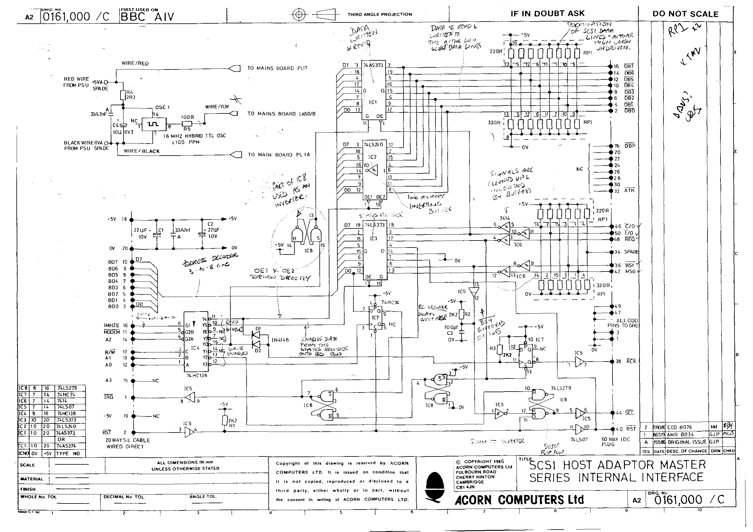
The original Acorn SCSI host adapter schematic is shown in the following diagram:
The host adapter design can be split into several logical blocks namely:
- 1 MHz bus termination
- Page Select clean-up
- Address decoder
- SCSI Data out latch and inversion
- SCSI Data in tristate and inversion
- Status byte latch
- Interrupt logic
- SCSI Acknowledge logic
- SCSI Select logic
- SCSI Bus termination
Each one of these blocks is described in the sections below.
1 MHz bus termination
The 1 MHz bus termination consists of 4x 2K2 Ohm resistor networks acting as both pull-up and pull-down resistors on all bus signals from the host. The resistors reduce signal reflection in the bus and ensure that signals do not ‘float’ if the 1 MHz bus cable is not connected.
IC1, IC5 and IC8a act as line-buffers for the 1 MHz bus. Acorn’s documentation states that the TTL fan-out of any device connected to the bus should be no more than 1; therefore, the line-buffers act to decouple any drive loading from the bus. As a side-effect, the line buffers also clean up the signals from the host to ensure clean logic signals to the rest of the host adapter.
Page Select clean-up
The Acorn BBC Micro’s page select (used to inform the adapter that a valid command is present on the host bus) has several issues around clock glitches caused by the clock-stretching methods used by the host hardware (this is covered in some detail by the Advanced User Guide documentation). Page clean-up is provided by IC10 which acts to synchronise the page selection with the 1 MHz Enable clock signal. Page clean-up is performed before the address decoding logic.
The page clean-up circuitry is not required by the BBC Master (as the page selection hardware in the host is provided by a dedicated custom IC); however, the page-select clean-up circuitry functions with both the BBC Micro and the Master.
Address decoder
A pair of 74LS138 ICs are used to provide address to command decoding on all 8-bits of the address bus (provided by IC6 and IC7). Commands are formed by the combination of the page select signal (that indicates the most significant byte of the command), the address bus (that indicates the least-significant byte of the command) and the Read/Write signal (that indicates the direction of the command).
ADFS uses the following commands to interact with the SCSI device:
- FC40 Read – Read SCSI data bus
- FC41 Read – Read SCSI status byte
- FC40 Write – Write SCSI data bus
- FC42 Write – Assert SCSI Select
- FC43 Write – Set/Clear interrupt enable flag
All commands interact with the logic of the host adaptor to function.
SCSI Data write latch and inversion
When the host performs a write SCSI data bus command (FC40WR) the adaptor latches the data byte on the host data bus using IC2. IC2 is tristated towards the SCSI bus by the set of NAND gates provided by IC13 and IC14. The output enable of IC13 and IC14 is, in turn, controlled by the SCSI I/O signal so that the SCSI data bus is only driven when the SCSI device is ready to receive. The NAND gates also act to invert the host data bus byte since all SCSI device signals are negative logic (i.e. 1 = off and 0 = on).
SCSI Data read tristate and inversion
The SCSI data bus input is latched and inverted by IC3. The output side of IC3 (towards the 1 MHz bus) is tristated. The output-enable is triggered by the FC40 Read command from the host.
Status byte read latch
The status byte latch acts the same as the data read function allowing the host to send a FC41RD command to read the 8 status bits via the host data bus (the command acts as an output-enable for IC4). The SCSI status byte functionality is specific to the Acorn ADFS implementation of SCSI and the status bits have the following meanings:
- Bit 0 – SCSI MSG signal
- Bit 1 – SCSI BSY signal
- Bit 2 – Always 0
- Bit 3 – Always 0
- Bit 4 – Interrupt flag
- Bit 5 – SCSI REQ signal
- Bit 6 – SCSI I/O signal
- Bit 7 – SCSI C/D signal
The SCSI signals are inverted logic so IC15 is used to invert the signals before they are latched by IC4.
Interrupt logic
The Acorn SCSI Host Adapter provides two pieces of logic to control the actions of the IRQ (interrupt request signal) to the host bus. The first part of the logic provided by one-half of IC10 sets if interrupts should be triggered or not. This is set by the host using the FC43WR command along with the setting of data bus bit 0. When the command is invoked the setting of data bus bit 0 controls the reset signal of a secondary latch provided by IC12. The secondary latch is responsible for setting and clearing the IRQ host bus signal based on the status of the SCSI REQ signal.
It should be noted that the output from the secondary interrupt latch towards the host bus is tristated by IC16 (a non-inverting buffer). The IRQ signal is only driven at the logic 0 level (as it is a not-IRQ signal); at logic level 1 the IRQ signal is floating to allow other devices to use the IRQ signal.
This functionality allows the host to either perform a blocking action (where the host sends a command and waits indefinitely for a SCSI device response) or a non-blocking action (where the host sends a command and then continues execution until an interrupt is signalled by the adapter).
Most ADFS interactions are driven by blocking actions however random-access reading and writing is an exception and uses the non-blocking method.
SCSI Acknowledge logic
All SCSI-1 data exchanges are controlled by an envelope of request (REQ) and acknowledge (ACK) signals. SCSI devices are asynchronous (i.e. there is no data ‘clock’ signal) as opposed to the Acorn 1 MHz bus which is synchronous (to the 1 MHz clock enable signal). The SCSI acknowledge logic provided by one-half of IC11 causes the host adapter to clear the SCSI ACK signal whenever the SCSI device asserts the REQ signal. In addition, the acknowledge logic asserts the ACK signal whenever the host performs a data bus read or write (using FC40RD or FC40WR commands).
The basic flow is that, for a write, the device sets REQ which the host detects via the status read command. Then the host performs a read command which sets the ACK signal. When the device next sets REQ, the ACK signal is cleared and the envelope starts again.
This logic is the primary purpose of the host adapter – to provide synchronous bus to asynchronous bus communication between the computer and the SCSI device.
SCSI Select logic
The SCSI select logic allows the host to signal to the device that it is selected. This must take place before any other SCSI actions can be performed. The SCSI selection is signalled by the FC42WR command that is latched via one-half of IC11. In response to the selection, the SCSI device will assert BSY (busy) for the host to know that selection was successful.
SCSI Bus termination
SCSI bus termination is provided by 2x 220R pull-up resistor networks and 2x 330R pull-down resistor networks. The pull-down resistors have a higher resistance than the pull-up resistors to ensure that, if no SCSI cable is connected, the SCSI data bus signals always read logic 1. As the SCSI data bus is inverted this means the data bus value will always be zero if no device is attached.
Acorn AIV Host Adapter
The Acorn AIV Host Adapter is similar to the Acorn SCSI Host Adapter and was developed for use with VFS (Acorn’s Video Filing System). The AIV adapter is designed to be fit internally to a BBC Master Turbo and is connected to the internal 1 MHz bus.
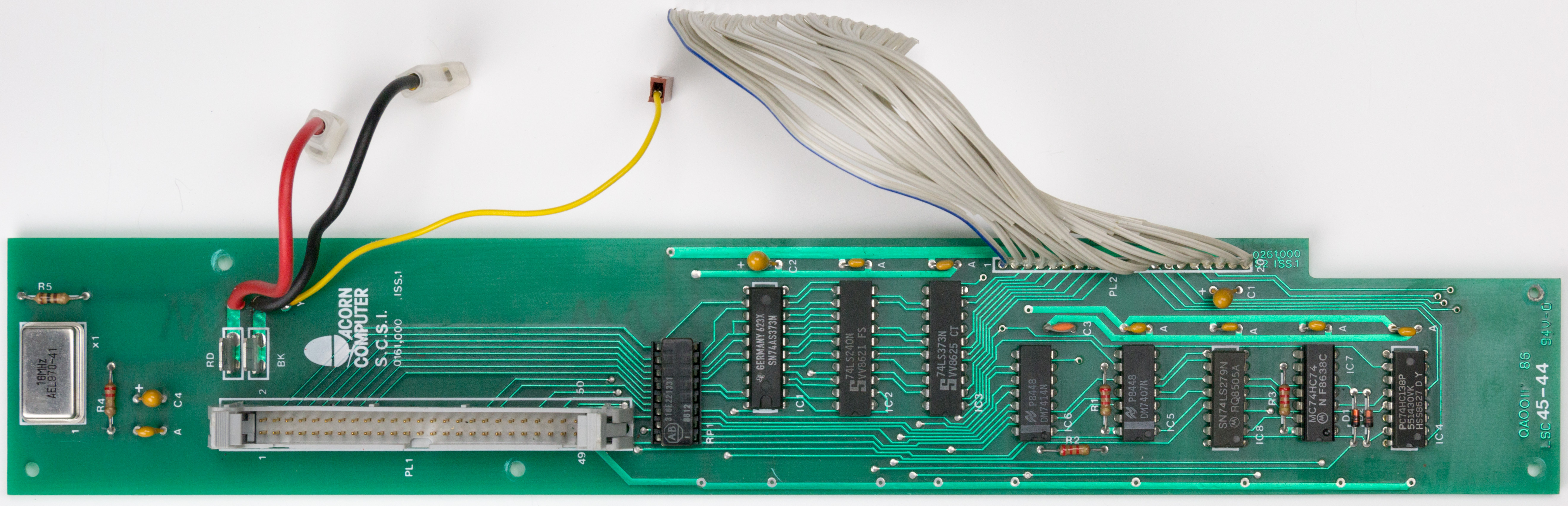
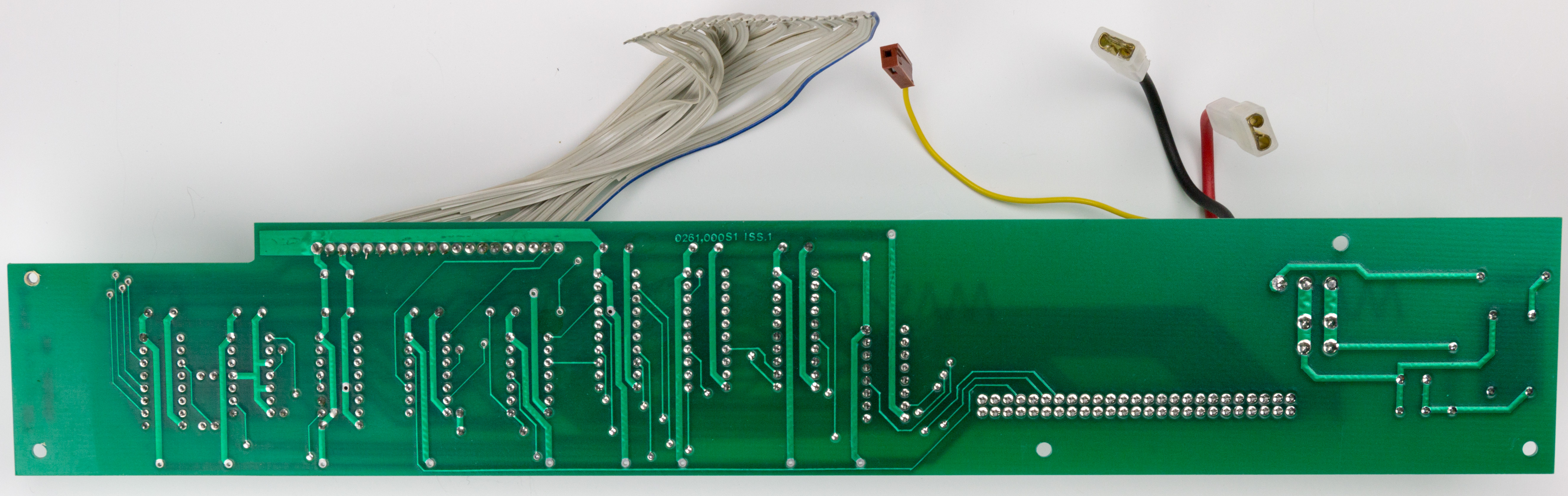
The original Acorn AIV SCSI host adapter (front and back) is shown in the following photographs:
The schematic for the Acorn AIV Host Adapter is shown in the following diagram:
It should be noted that, due to hardware differences between the AIV board and the host adapter board, it is not possible to use the boards interchangeably although the overall operation logic is similar. The following sections explain the differences between the AIV board and the host adapter.
SCSI data write latch
On the Acorn SCSI board IC13 acts as both an open-collector and an inverter on the data bus byte. The AIV board uses IC1 but this chip does not invert the outbound data bus byte (instead this is done by VFS itself). The AIV board uses a 74LS240 just like the Acorn SCSI on the data bus input; so, both boards invert the data bus input.
SCSI Select and IRQ logic
The Acorn AIV board uses a 74LS279 chip (IC8 – ‘not SR latch’) as part of the select and IRQ handling logic (the Acorn SCSI Host Adapter uses a combination of NAND gates and a D-type flip-flop). Overall the resulting logic is the same. The AIV board uses the 2 'unused' not SR latches as inverters (replacing hex inverter gates used on the Acorn SCSI board).
Part of IC8 is incorrectly labelled in the Acorn schematic. The inverter configuration on the write enable latch is marked as an SR latch (when it is a ‘not SR latch’). Consequently, it's wired with the reset to +5Vs but, as negative logic, it should be wired to 0Vs (like the other instances).
SCSI status byte and reset
IC3 on the Acorn AIV Host Adapter and IC4 on the Acorn SCSI Host Adapter are used as the status byte latch. On the Acorn SCSI board bits 2 and 3 are unused and tied to ground. On the AIV board, status bit 2 is connected to the outside of an open-collector buffer on the reset pin of the SCSI bus. The purpose of this status bit is unknown; however it is likely that VFS uses it to detect if a device is connected.
IRQ status bit
Bit 4 of the SCSI status byte is used for IRQ handling on both boards however, on the AIV board there is no inverter between the IRQ logic and the status bit. This means that VFS expects the IRQ flag to be negative logic (unlike all the other status bits). On the Acorn SCSI board the IRQ flag is positive logic.
Read/Write command NAND logic
The AIV board uses two diodes (D1 and D2) and a pull-up resistor on the read/write command lines in place of the NAND and inverter found on the Acorn SCSI board. From a logic perspective, these perform the same function (the diodes form an AND gate just like the combined NAND and inverter).
Host commands
Since the address bus on the AIV board is only four-bits wide, the command addresses are different compared to the Acorn SCSI Host adapter due to the most significant nibble of the commands being omitted:
- MODEM0 Read – Read SCSI data bus
- MODEM1 Read – Read SCSI status byte
- MODEM0 Write – Write SCSI data bus
- MODEM2 Write – Assert SCSI Select
- MODEM3 Write – Set/Clear interrupt enable flag
Page select clean-up
The AIV board does not perform clean-up of the page select signal (since IC15 in the BBC Master Turbo does not produce the same glitchy page select as the BBC micro).
CMOS Levels – not TTL
The internal 1MHz bus of the Master is 5V CMOS (the external Master bus and BBC external bus are 5V TTL) - this does not have a significant impact of the AIV board design (since the input buffer chips work for both CMOS or TTL).
The AIV board uses a 74HC138 address decoder as the 1MHZE and R/W lines are CMOS levels, so a 74LS138 (as used on the external host adapter) will not function (it is designed for TTL levels).