Overview
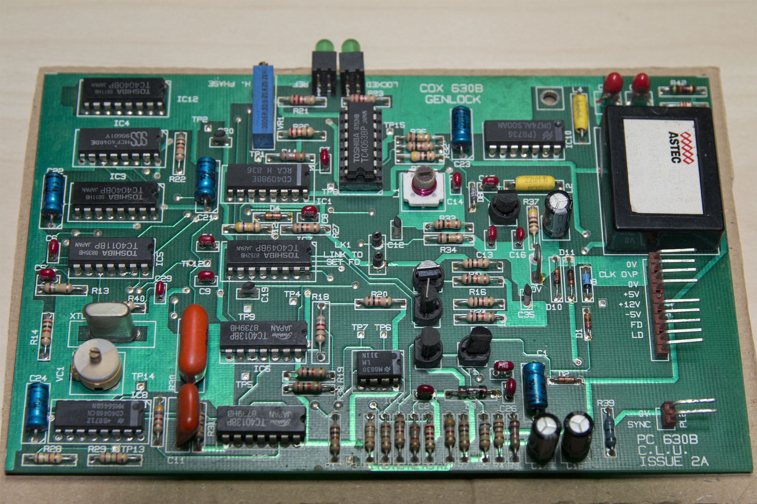
The Cox 630B genlock board is an add-on which works with both the BBC Micro and the BBC Master series computers. Although this is not a normal part of a Domesday AIV system, it can be a useful tool when experimenting with video overlays and mixing. Since very little information is available on the web about this board this article provides information about how the board is connected to the BBC Master and the general functionality of the board itself.
In order to combine analogue video signals (before the advent of digital frame-store mixers) it was necessary to ensure that all video sources were synchronised to the same video clock. A genlock (short for generator locking) is a device which 'locks' the video clock of a device to an external clock source. Note that the 630B is purely a genlock device, it does not perform any mixing or processing of the video signal itself. Both the BBC Micro and the BBC Master have a fairly poorly designed 16 MHz video clock; the on-board clock is inaccurate and makes it difficult to sync the BBC Micro or Master to an external clock source. Therefore the Cox 630B (just like the Acorn AIV SCSI adapter) provides it's own 16 MHz video clock that is wired to the computer's motherboard and replaces the clock signal to the computer's video processor.
Connections
The Cox 630B provides 2 SIL connectors, a 10 pin SIL for the video clock, power and external 16 MHz clock and a 2 pin SIL for the external video clock input. The connections are as follows (the colours denote the standard cable that comes with the board):
10 pin SIL
0V - Black wire: Ground
CLK O\P - Brown wire: 16 MHz clock out to computer
0V - Red wire: Ground
+5V - Orange: +5V supply from computer
+12V - Not connected: Not required (usually acts a 'key', i.e. it is blocked to prevent the connector being reversed)
-5V - Green: -5V supply from computer
FD - Blue: Field Drive (this is the Vertical Sync from the computer)
LD - Purple: Line Drive (this is the Horizontal Sync from the computer)
NC - Not connected
NC - Not connected
2 pin SIL
0V - This is the signal ground for the external clock input (note: this is not the same as ground on the 10 pin SIL)
SYNC - This is the external clock input signal
Connecting to the BBC Master
All of the power connections should be wired to the appropriate power terminals of the BBC Master's motherboard. If you don't wish to adapt the power supply terminals to allow for the extra connections you can solder the wires directly to the correct wire-links that can be found next to the power connectors on the motherboard. The correct wire links are as follows (Note: Wire links on the motherboard are marked as L followed by a number; these are not the same as Links which are denoted by LK - please check the Master's schematic diagram for details):
L5 - Ground
L4 - +5V
L10 - -5V
The clock O\P should be connected to the 'B' pin of LK60. The jumper on LK60 should be removed (which disables the on board video clock) before fitting the wire to the motherboard. Note that, without the A-B jumper on LK60, you will not get any video output from the Master unless the Genlock board is correctly connected.
The Field Drive should be connected to pin 4 of IC25 (VS) and the Line Drive should be connected to pin 5 of IC25 (HS)
Using the Genlock board
To operate the genlock board you simply need to power up the Master. If there is no external sync clock connected to the Genlock board it will automatically use its own local clock. There are two status LEDs on the top-edge of the board. When the board has successfully locked to a clock signal (either internal or external) the LOCKED light will be on. When the board is synchronised to an external video clock the REF light will be on.
If necessary, the on-board crystal can be tuned using VC1 on the Genlock board. This variable capacitor allows you to set the oscillator the correct speed. You will need to connect an oscilloscope to the CLK O\P signal in order to measure the clock speed before trimming.
The H. Phase potentiometer on the 630B allows you to adjust the horizontal phase of the clock. This has the effect of moving the synchronised picture up and down relative to the external clock sync; this allows the output from the computer to be horizontally aligned with other pictures if required.