This guide is obsolete and has been replaced.
Click here for the improved (and corrected) calibration guide for the Pioneer LD-V4300D and LD-V4400 LaserDisc players.
Contents
Overview
This article covers the mechanical player adjustment (calibration) of the Pioneer LD-V4300D LaserDisc player as per the service manual. The service manual appears to be mainly copied directly from the LD-V8000 service manual without any update which means several of the steps are extremely difficult to follow (and others incorrect). The calibration steps in this article have been rewritten as necessary and new diagrams and additional information and notes added to make the process clearer wherever possible. This article does not cover the electrical calibration steps (page 119 of the original service manual) - only the mechanical calibration.
There is, of course, no guarantee that the calibration steps suggested here are correct. You should note that attempting to calibrate a LaserDisc player can not only cause the player to stop functioning, it can also damage the player (and even you, since the 240V/110V voltages in the exposed power supply are potentially deadly). Proceed with calibration at your own risk and ensure you have studied the details of each step (and understood the requirements) before attempting on a player. If you are unsure, don't have the required equipment or don't have the required electronics skills - do not attempt to calibrate your player.
Service mode playback
The Pioneer LD-V4300D has 3 possible modes of playback in service mode:
- Tracking servo loop open
- Tracking servo loop closed - playback
- Tracking servo loop closed - still-frame
When tracking is open the slide drive is disengaged and the player tracks only using radial tracking. The slide drive can be freely moved backwards and forwards (even by hand for speed). If the slide drive is moved the player makes no correction.
When tracking is closed and in playback the player acts as per the normal playback mode - both radial tracking and the slide drive are engaged.
When tracking is closed and in still-frame the player acts as per the normal still-frame mode - both radial tracking and the slide drive are engaged and the player will attempt to remain tracked on a single frame.
Service mode focus balance selection
The focus balance selection switches between using VR6 (when focus balance is 1) and VR7 (when focus balance is 0) to set the maximum radial tracking gain. The purpose of these two settings is not documented in the service guide, however they appear to set the minimum (VR7) and maximum (VR6) tracking ranges used by the player when balancing the gain of the focus loop against the tracking (i.e. once the tracking level drops to a certain point the player will increase the focus gain and vice-versa to maintain lock on the track).
Service mode tilt control
The LD-V4300D service mode allows the tilt mechanism to be disengaged (off) without the need to disconnect the tilt motor physically (unlike similar plays such as the V8000). Provided the player remains in service mode throughout the calibration procedure, there is no need to disconnect connector CN4. Leaving CN4 connected allows manual override of the tilt position which is required for certain calibration adjustments.
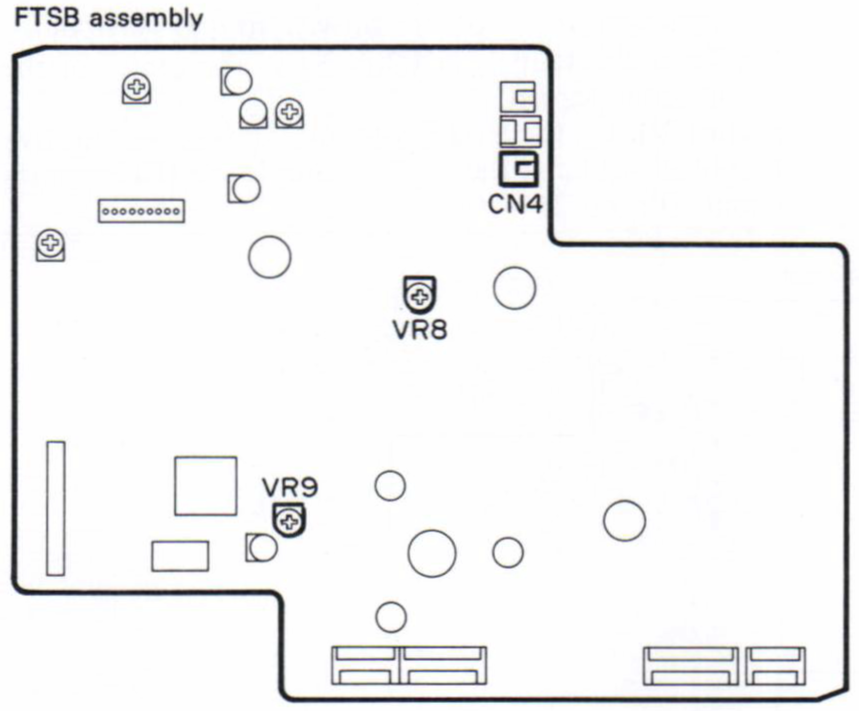
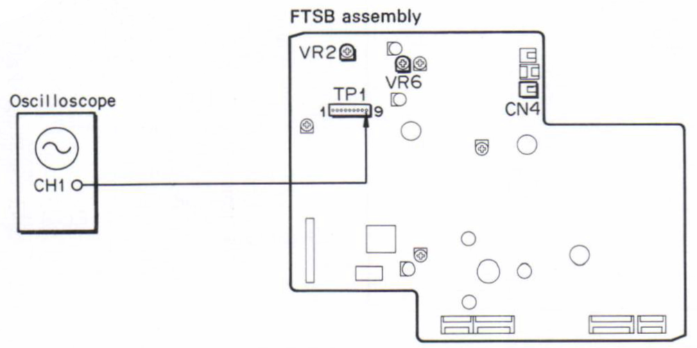
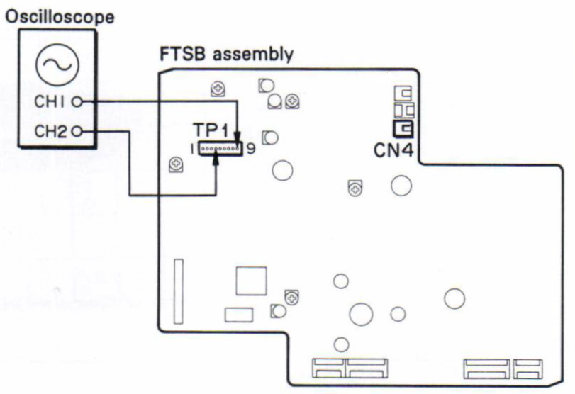
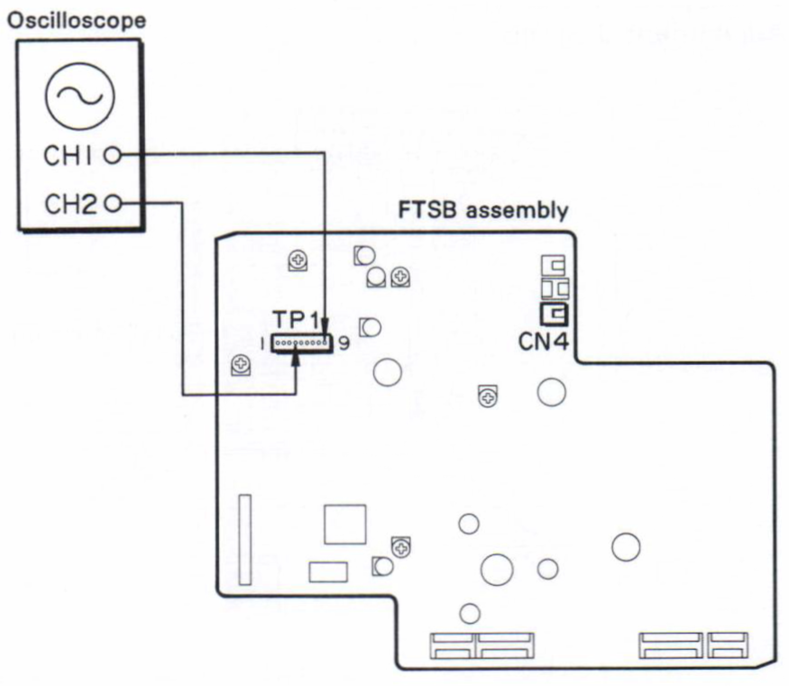
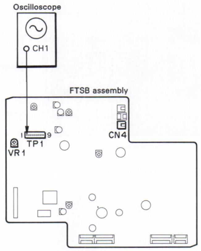
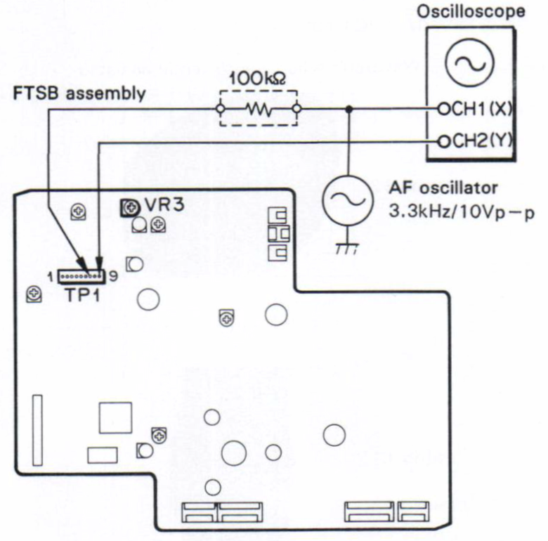
FTSB module adjustment points
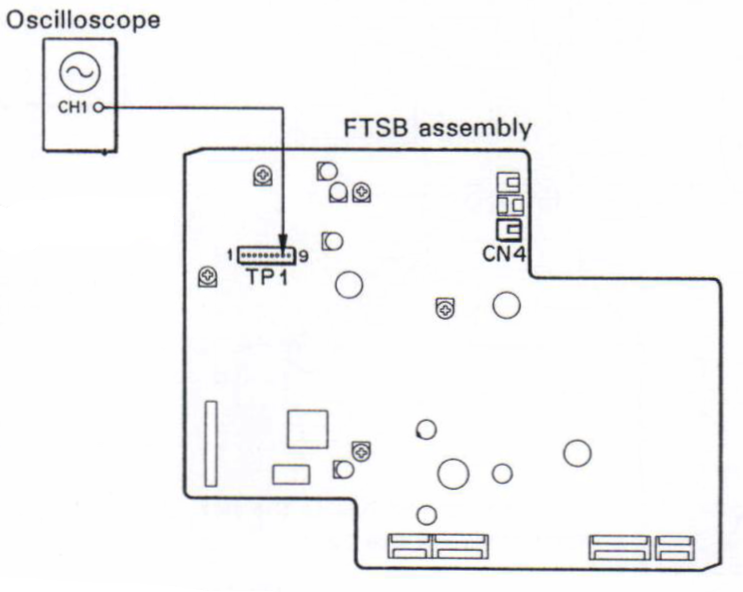
The various potentiometers on the FTSB module are shown in the following diagram:
The functions of the various potentiometers are as follows:
- VR1 - RF Gain
- RF Gain adjustment
- VR2 - Tracking Balance
- Grating temporary adjustment and tracking balance adjustment
- VR3 - Tracking Gain
- Tracking servo loop gain adjustment
- VR4 - Tilt Offset
- Tilt sensor inclination adjustment (8)
- VR5 - Focus Gain
- Focus servo loop gain adjustment
- VR6 - Focus Balance (T.E)
- Grating temporary adjustment and tracking balance adjustment
- VR7 - Focus Balance (C.T)
- Focus error balance adjustment
- VR8 - Tilt Gain
- Tilt gain adjustment
- VR9 - Tilt Balance
- Tilt gain adjustment
Adjustment should be made with a small, insulated flat-blade screwdriver. Care should be taken to rotate the variable resistors gently and not exceed the maximum limits of the variable resistor in either direction.
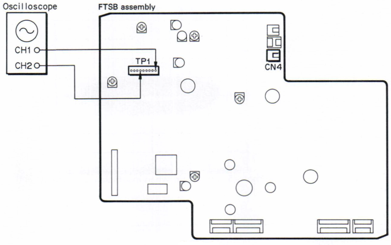
Accessing the FTSB module test-header
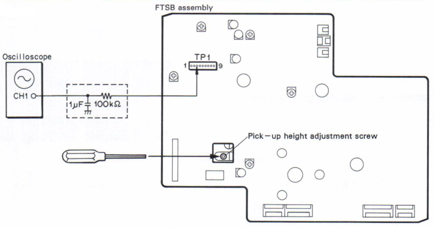
Most of the calibration methods require measurement with an oscilloscope that must be connected to the service header on the FTSB module. The original service manual requires 100Kohm resistors for some tests and a simple RC filter (using a 100K resistor and 1uF capacitor). As the test header on the FTSB module is quite small, it's a good idea to construct a simple adaptor with larger connections to assist connection to the test equipment. The following schematic shows the (very simple) circuit required for the adaptor:
A simple PCB design for the adaptor can be found in the following Github repository (in KiCAD 5 format including Gerber files for PCB production).
Pioneer LD-V4300D Service Adaptor Github
The completed service adaptor PCB is shown in the following picture and is connected to the player using a 9-pin JST-EH connector cable:
Service and Calibration LaserDisc
Servicing requires an 8" reference disc from Pioneer. The disc part number mentioned by the original service manual is no longer available; The replacement part number is GGV1069 and (at the time of writing) is still available for sale by Pioneer.
The contents of the disc are shown in the following table (note, this table is a little messy due to a recent change to the website software - it will be fixed soon):
| Radius & Time | Video | Chapter- number | Picture- stop | Audio | Extended Code | |||
| Frame-number | Contents | Channel 1 | Channel 2 | CX | ||||
| 0 | Lead-in | OFF | ||||||
| 30sec | 1 | H, V Bar | 1 | 475 | 1kHz (100%) | |||
| 30sec | 901 | Multi burst | 2 | |||||
| 30sec | 1801 | White (100%) | 3 | |||||
| 30sec | 2701 | Black (7.5%) | 4 | Non Modulation | ||||
| 30sec | 3601 3901 4201 | Composite test Signal | 5 | |||||
| 6 | ||||||||
| 7 | ||||||||
| 30sec | 4501 4801 5101 | Stair Step | 8 | 1kHz (100%) | Non Modulation | |||
| 9 | ||||||||
| 10 | ||||||||
| 30sec | 5401 5701 6001 | Color Bar | 11 | Non Modulation | 1kHz (100%) | |||
| 12 | ||||||||
| 13 | ||||||||
| 30sec | 6301 | White (100%) | 14 | 20Hz (90.5%) | ||||
| 30sec | 7201 | Magenta | 15 | |||||
| 30sec | 8101 | Blue | 16 | 1kHz (4%) | ON | |||
| 30sec | 9001 | Red | 17 | |||||
| 30sec | 9901 | Green | 18 | Non Modulation | ||||
| 30sec | 10801 | Blue | 19 | 1kHz (75%) | ||||
| 30sec | 11701 | Red | 20 | CX test signal | Non Modulation | |||
| 30sec | 12601 | Green | 21 | Non Modulation | CX test signal | |||
| 30sec | 13501 | Composite test Signal | 22 | 1kHz (40%) | OFF | |||
| 30sec | 14401 | Cross | 23 | White Noise | Non Modulation | |||
| 30sec | 15301 | Dot | 24 | Non Modulation | White Noise | |||
| 30sec | 16201 | Still picture | 25 | 3.15kHz (16.2%) | ||||
| 30sec | 17101 | Video sweep | 26 | Non Modulation | ||||
| 30sec | 18001 | Test pattern | 27 | |||||
| 30sec | 18901 | Ramp | 28 | 1kHz (100%) | ||||
| 30sec | 19801 | Composite test Signal | 29 | 1kHz (75%) | ||||
| 30sec | 20701 | APL bounce | 30 | 1kHz (40%) | ||||
| 30sec | 21601 | Color Bar | 31 | Sweep 20Hz-20kHz | ||||
| 30sec | 22501 | H, V Bar | 32 | |||||
| 60sec | 23401 | Motion picture
(Last Frame) | 33 | Sound (main) | Sound (sub) | |||
| 24301 | 34 | |||||||
| 25200 | ||||||||
| Lead-out |
Service remote control
A service remote control is required for calibration. The RM Series RMC12010 remote is a 3rd party service remote clone available from sites such as Ebay. The RMC12010 remote required is shown in the following picture:
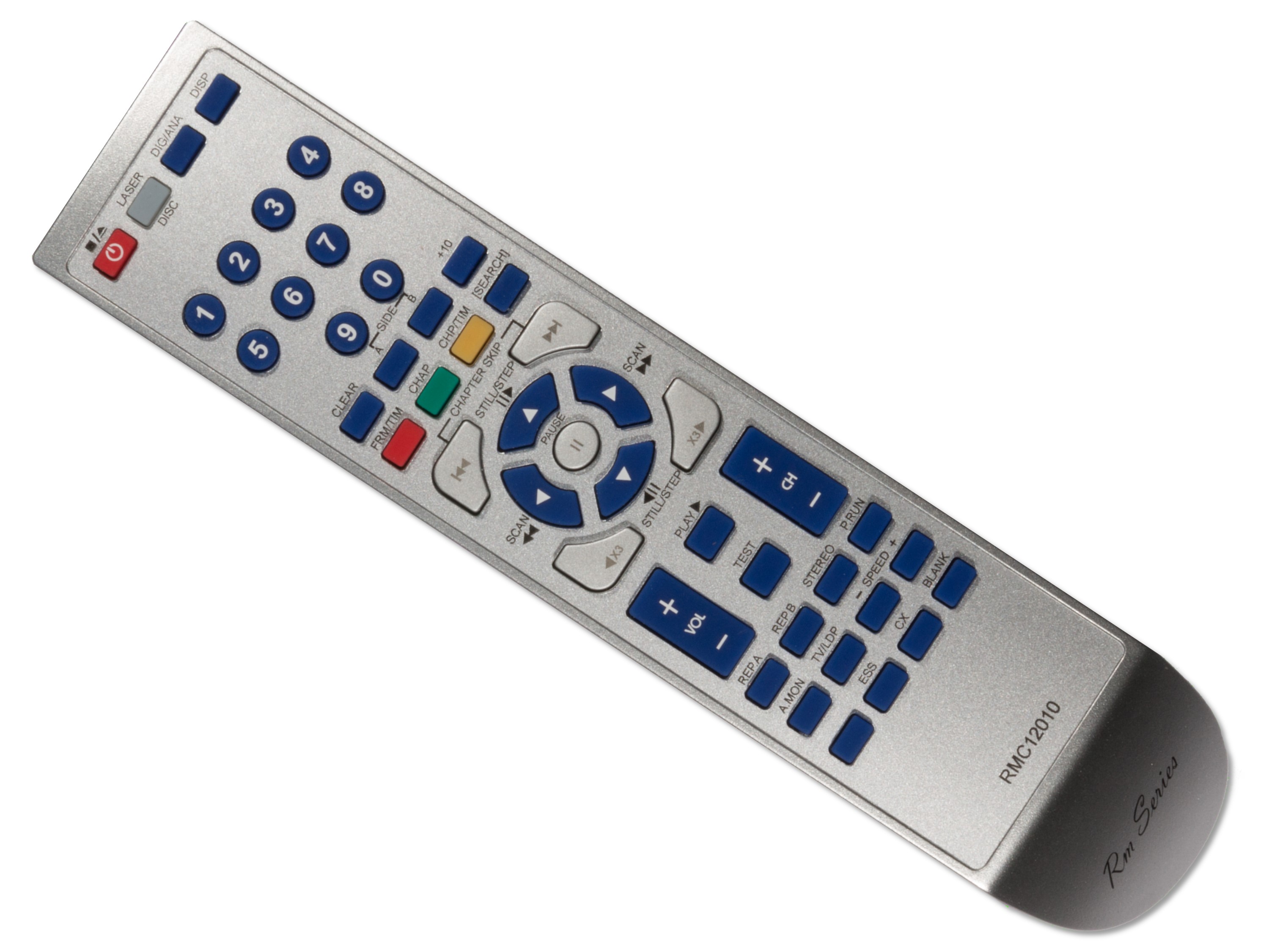
Please note that the RMC12010 remote does not correctly map the MULTI-REV and MULTI-FWD buttons for the LD-V4300D (and these buttons are required for the calibration process). The correct codes for these buttons are given in the Pioneer LD-V4300D Overview page. You can use either a combination of the RMC12010 and the Pioneer CU-V113A remote, or use a programmable remote and the key-codes provided on the linked page from this site.
Pioneer service remote controls produced after the GGF1067 do not seem to produce the correct key-codes for MULTI-REV or MULTI-FWD either. Again, a combination of the CU-V113A and the service remote can be used.
The mapping of the RMC12010 service remote keys (to the original service remote keys) are shown in the following table (note: the most important one to know is [ESS] followed by [TEST] which switches the player into test mode (there is no need to power on holding DISPLAY or use any DIP switch settings on the LD-V4300D)):
| Function | Operation | ||
| LD-V4300D | Service Remote | RMC12010 remote | |
| Open | Press the [OPEN/CLOSE] key in the stop mode. | Press the [REPEAT MODE (REPEAT B)] key. | |
| Stop | Press the [OPEN/CLOSE] key in the play mode. | Press the [REPEAT A] key.
Press the [REJECT] key in the play mode. | |
| Play
Video and audio are on Tracking is open | Press the [PLAY] key in the stop mode. | Press the [TV/LDP/ key.
Press the [PLAY] key in the stop mode. | |
| Still | Press the [PLAY] key during TRACKING OPEN in the play mode. | Press the [CX] key in the play mode.
Press the [PLAY] key during TRACKING OPEN in the play mode. | |
| Tracking open | Press the [STEP FWD] key in the play mode.
Press the [PLAY] key in the play mode. | Press the [STEP FWD] key in the play mode.
Press the [PLAY] key in the play mode. | [BLUE UP] |
| Tracking closed | Press the [STEP REV] key in the play mode.
Press the [PLAY] key during TRACKING OPEN in the play mode. | Press the [STEP REV] key in the play mode.
Press the [PLAY] key during TRACKING OPEN in the play mode. | [BLUE DOWN] |
| Slider in | Press the [SCAN REV] key. | Press the [SCAN REV] key. | [BLUE RIGHT] |
| Slider out | Press the [SCAN FWD] key. | Press the [SCAN FWD] key. | [BLUE LEFT] |
| Tilt servo off | Press the [SPEED DOWN] key. | [SPEED-] | |
| Tilt servo on | Press the [SPEED UP] key. | [SPEED+] | |
| Tilt decrease & servo off | Press the [SKIP REV] key. | [CHAPTER SKIP REV] | |
| Tilt increase & servo off | Press the [SKIP FWD] key. | [CHAPTER SKIP FWD] | |
| Display on | Press the [DISPLAY] key. | ||
| Display off | Press the [AUDIO MONITOR] key. | ||
| Search address entry | Press the [+10] key in the play mode. | Press the [+10] key. The last address searched will be displayed | |
| Search address input | Input the address using [0] through [9] keys. | ||
| Search execute | Press the [CHAPTER/FRAME] key. | ||
| Focus balance = 0 | Press the [MULTI FWD] key during playback. | ||
| Focus balance = 1 | Press the [MULTI REV] key during playback. | ||
| Plunger pull | Press the [PAUSE] key. | [PAUSE] | |
| Plunger release | Press the [REJECT] key. | [POWER] | |
| Return to test mode menu | Press the [DISPLAY] key. | ||
| Go to diagnosis mode | Press the [TEST] key. | [ESS] then [TEST] | |
| Cancel test mode | Press the [ESC] key. | [ESS] |
Using the player with the disc tray removed
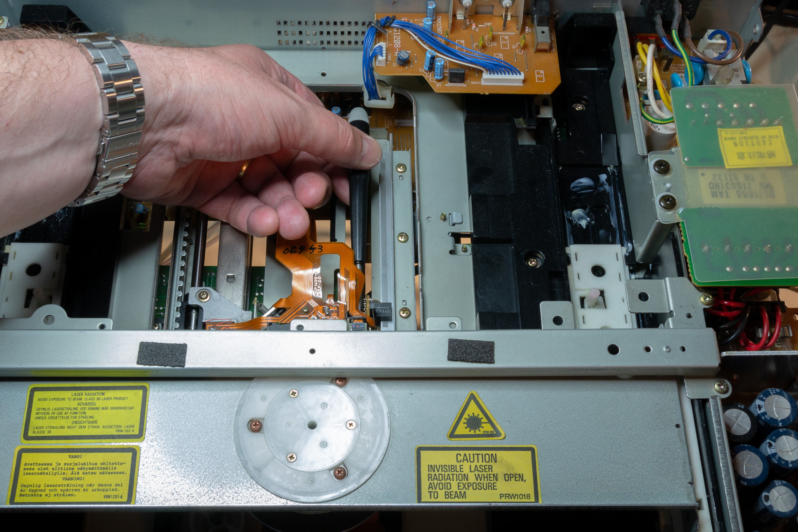
In order to perform the calibration steps it is necessary to remove the disc tray. When the disc tray is removed the player will attempt to close the tray on power up. To get the player to start correctly it is necessary to power up the player and then press the micro-switch at the back of the player manually.
Lifting the player during calibration - Important!
Many of the adjustments require you to access the underside of the player to reach the adjustment screws and potentiometers. When the player is horizontal on the workbench lift from the left side of the player so the power supply (on the right) is on the bench when the left side is raised. This lowers the chances of you putting your fingers into the live power supply during calibration. Putting your fingers inside the power supply during testing will lead to a very quick end to you adventures in player maintenance and repair. Be very careful of the power supply at all times.
It is also possible to lift the player by simply suspending it between two boxes; this reduces the need to lift the player during calibration.
Plunger pull/release
Note that several of the calibration steps below call for the optical slider to be locked in place; this is performed using the plunger pull/release controls on the service remote as noted above.
Tilt gain adjustment (1)
Purpose
To adjust the gain of tilt servo according to the gain rank of the tilt sensor.
Symptoms when incorrectly adjusted
Hunting of the tilt servo and increased crosstalk due to an increased insensitive range of the tilt servo.
Measurement equipment & jigs
Screwdriver (flat bladed)
Adjustment points
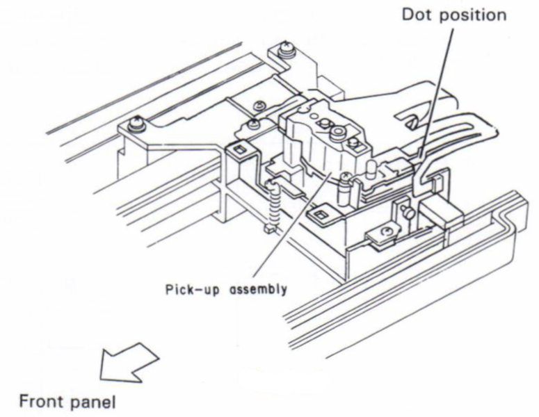
VR8 on the FTSB assembly:
Adjustment procedure
Check that VR9 is set to its mechanical centre position. There is no need for the player to be powered up or in service mode for this calibration.
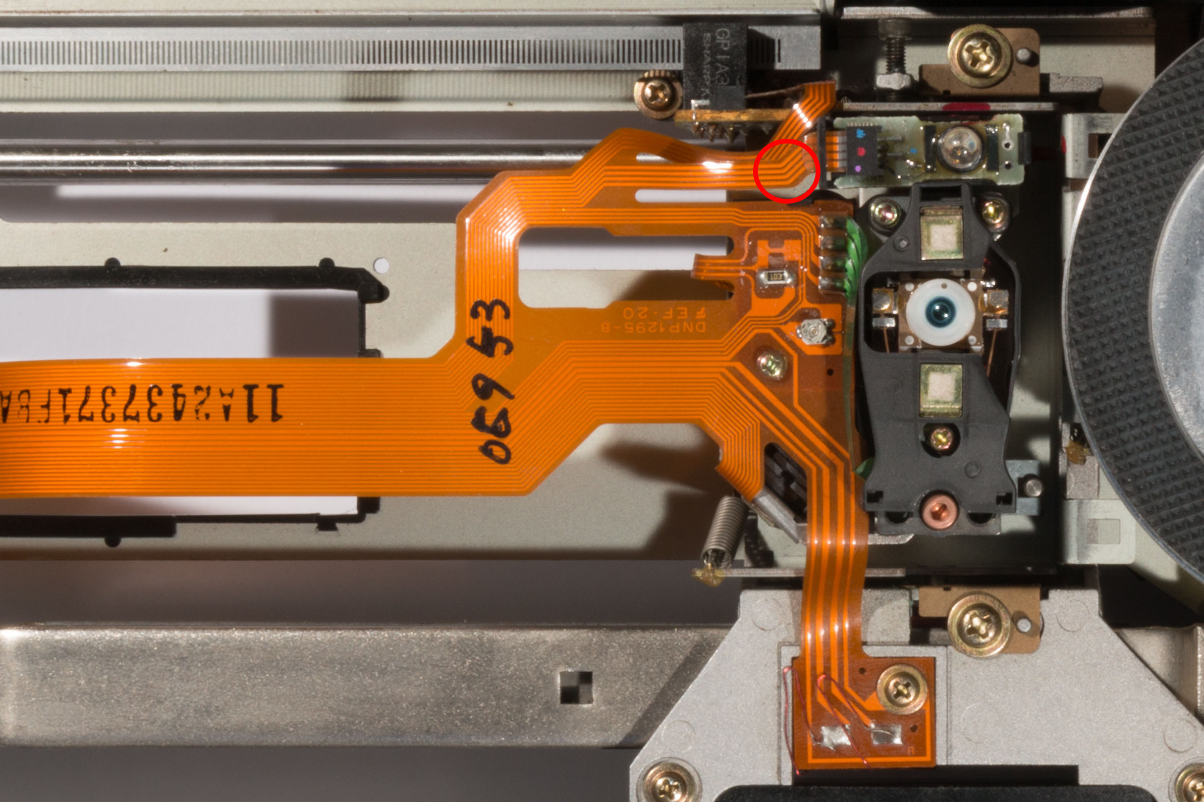
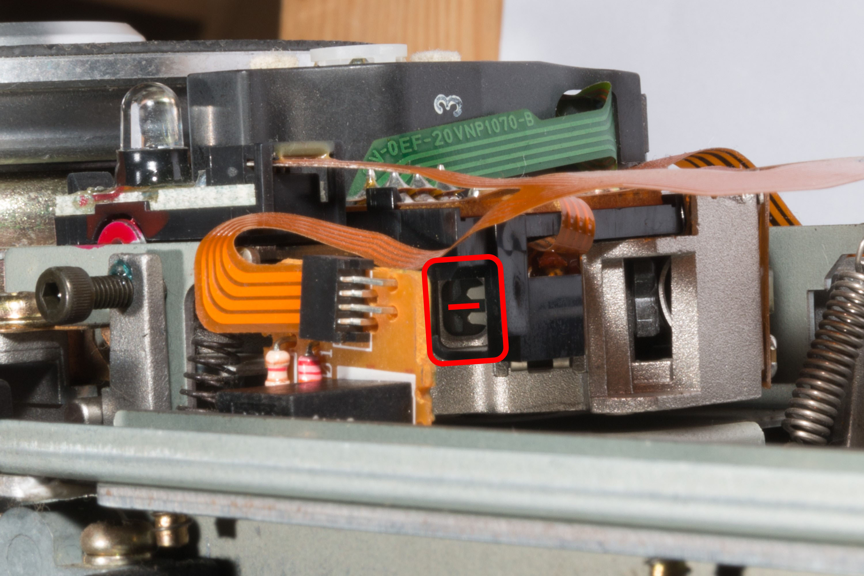
Check the colour of the dot on the flexible cable located at the side of the tilt sensor. (Fig. 1-1). There are three dot conditions: adjust VR8 on the FTSB board according to the following code.
- Red dot: Turn VR8 fully clockwise.
- Blue dot: Turn VR8 fully counter clockwise.
- No dot: Set VR8 to its mechanical centre position.
Adjustment diagrams
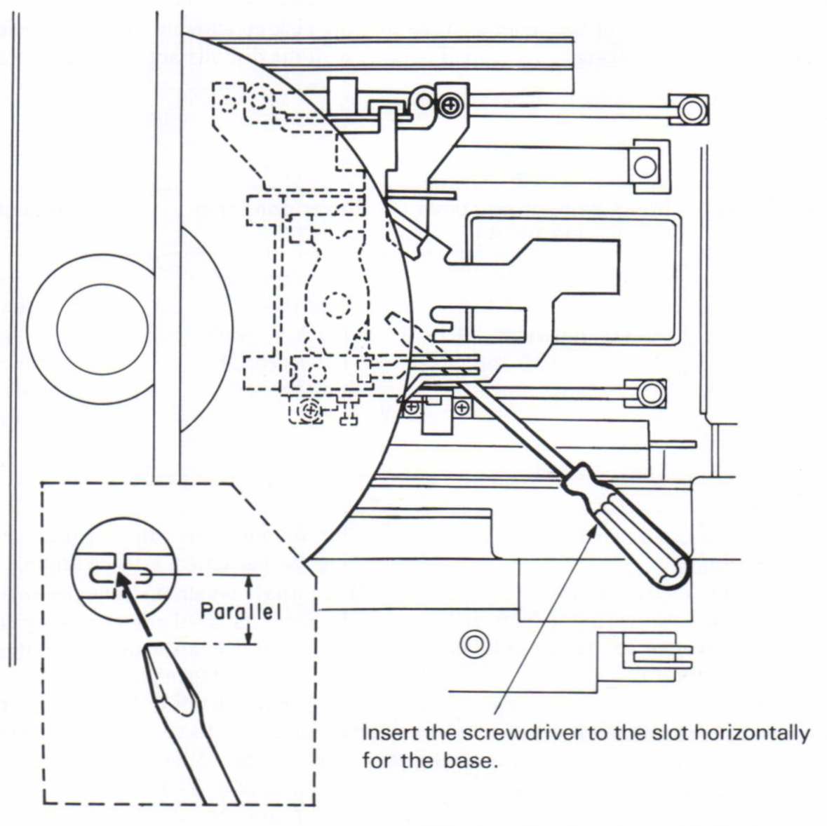
Grating temporary adjustment and tracking (TRKG) balance adjustment (2)
Purpose
Set the laser beam (which is divided into three by the grating) so that it is directed to the optimum position on the playback track - this causes the tracking error signal amplitude to be as high as possible.
Setting the offset voltage of the tracking servo to 0V to cause the tracking signal to be balanced (symmetrical) above and below the 0V centre-point.
Symptoms when incorrectly adjusted
Disc playback is impossible. Player jumps between tracks randomly.
Measurement equipment & jigs
- Screwdriver (flat bladed)
- Oscilloscope
- Test disc: GGV1069
Measurement equipment connecting points
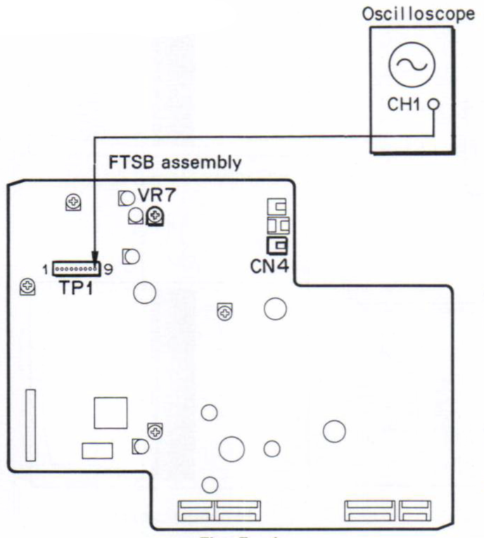
Oscilloscope: On FTSB assembly - CH1: Between TRKG ERROR (TP1-9) and GND
Player condition
- Service mode
- Tracking servo loop open
- Tilt servo off
- Focus Balance 0
Adjustment points
- Grating adjustment screw in the pick-up assembly
- VR2 and VR6 on FTSB assembly
Adjustment procedure
Grating temporary adjustment
- With the player set horizontally, play the test disc in service mode.
- Press the DISPLAY key on the remote so the frame number is displayed on the TV screen (if not already displayed).
- Open the tracking servo loop.
- Using the SCAN key, move the pick-up to a position around frame 20,000.
- Connect the oscilloscope to TP1-9 (TRKG error) to observe the waveforms.
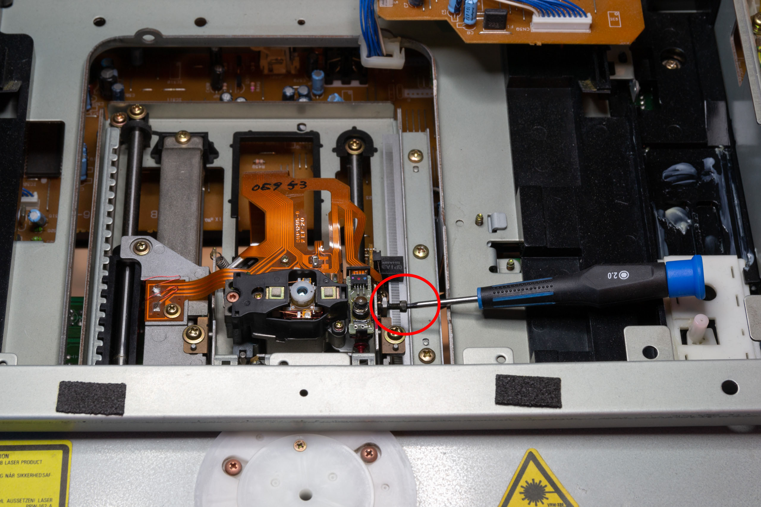
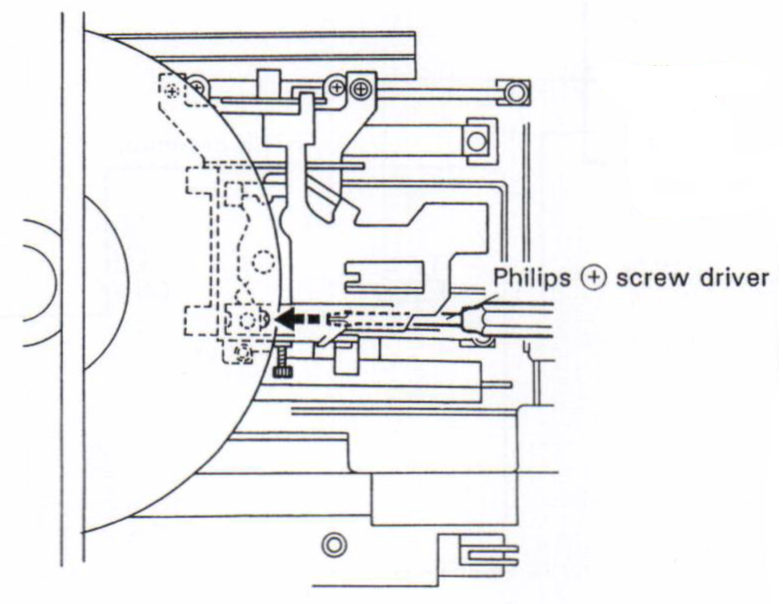
- Insert the flat bladed screwdriver (small) into the grating adjustment hole horizontally (as shown in the adjustment diagram).
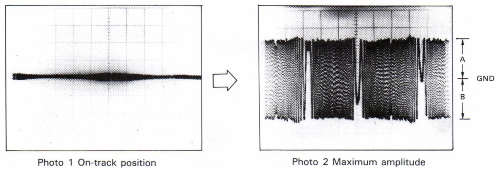
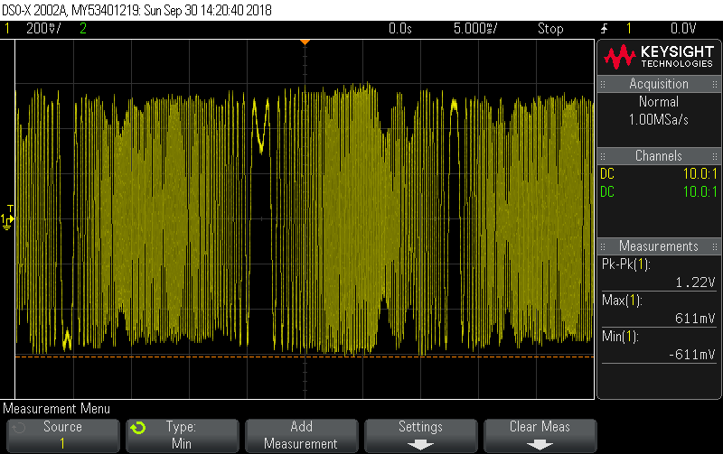
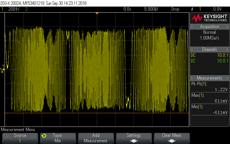
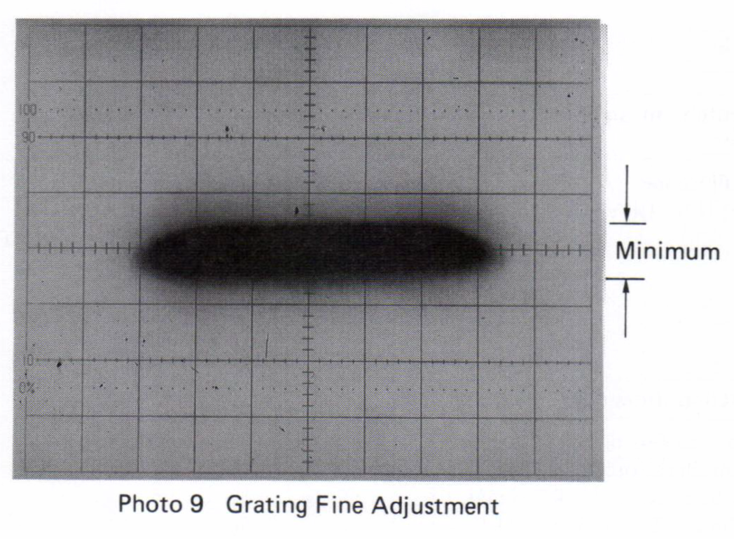
When the grating adjustment screw is turned, the tracking error waveform alternates between large and small. After the waveform amplitude becomes small, find the position where the waveform shows a smooth envelope as shown in photo 1. This state is called the "on-track" or "null" position. Note: This adjustment is very small; the maximum extent of the adjustment is less than a quarter turn of the screwdriver - be very careful to use minimal force as the adjustment point is easily damaged.
(When adjusting the grating with the small screwdriver (flat-bladed), the pick-up assembly tends to shift toward the inside of the disc, use the service remote to lock the pick-up assembly in place before performing the adjustment. - When the grating adjustment screw is turned counter clockwise slowly, the amplitude of the tracking error waveform gradually becomes larger. Set it to the position where the waveform amplitude is as large as possible (Photo 2).
- Once the grating is adjusted, select focus balance 1 and set the tracking error to the maximum possible amplitude using VR6 (FOCS BAL). Usually this is a simple case of setting VR6 to its maximum extent. Once adjustment is complete, change back to focus balance 0. Note: The maximum amplitude should be around 1200mV peak-to-peak.
- Close the tracking servo (into still frame or playback mode) to make sure that a picture on the screen is normal.
Note: In step 9 - 'normal' means that the picture is relatively clear and stable (pending the rest of the calibration). If the picture is rolling, flickering or distorted repeat the calibration procedure. If, after repeated recalibration, a reasonable picture is not possible, it is very likely that the pick-up tracking (see adjustment 4) is too far out of calibration to allow the player to operate.
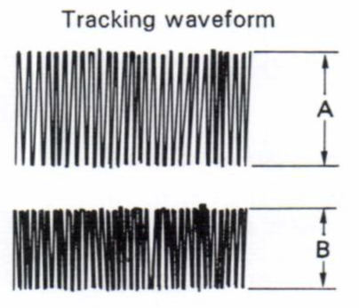
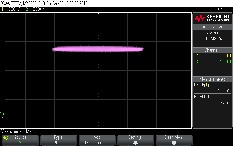
TRKG (Tracking) balance adjustment
- Set the player to the stop mode and raise it so it is vertical, then play the test disc in the service mode (tracking servo loop open).
(Note: If the disc cannot be played in this condition, set the player horizontally and engage the service mode to start playing the disc and then raise the left side of the player slowly, so it is vertical.) - Set the oscilloscope's GND point to the centre of the oscilloscope screen.
- Adjust VR2 on the FTSB assembly so that the positive amplitude (A) and the negative amplitude (B) becomes equal. (Photo 2)
Adjustment diagrams
Waveforms
Oscilloscope range: DC 50 mV/div., 5 mS/div.
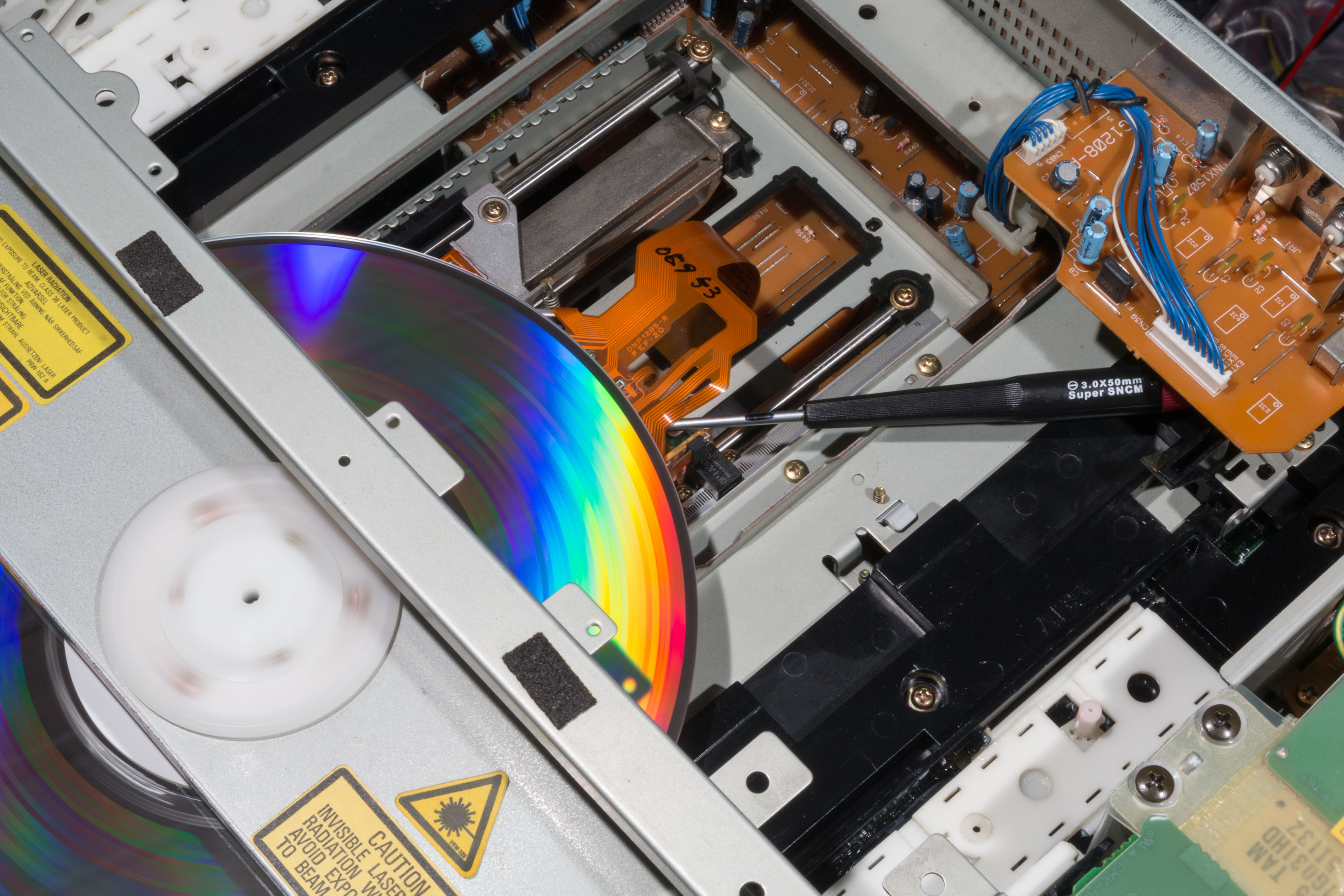
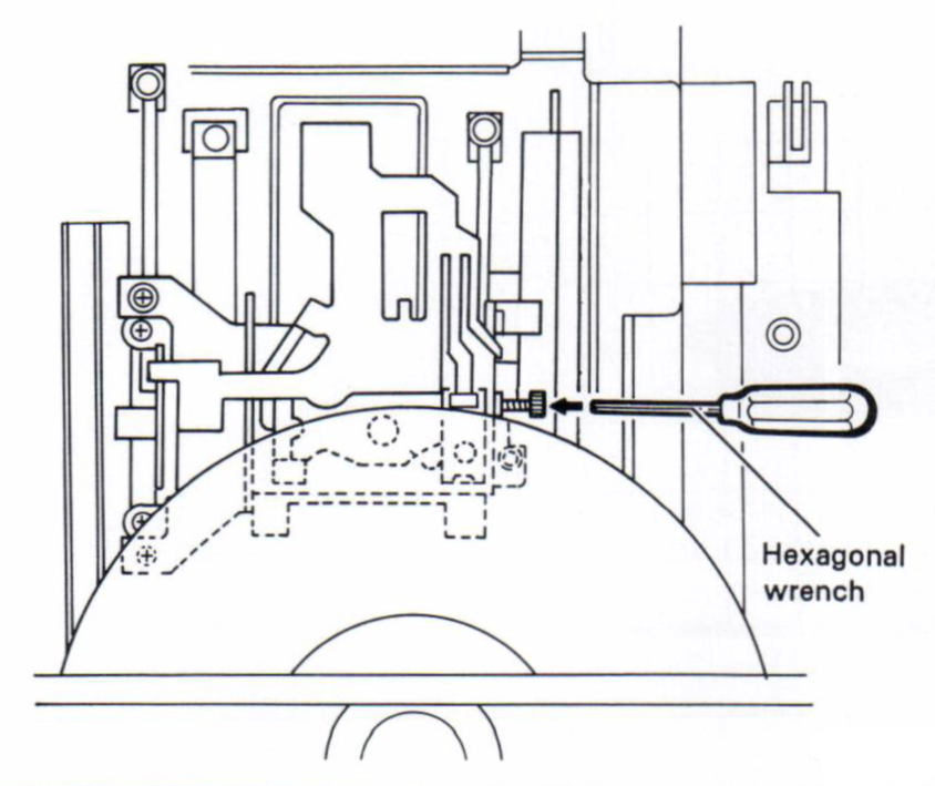
Pick-up height adjustment and drive shaft levelness adjustment (3)
Purpose
Adjust the inclination of the slider shaft so that the pick-up assembly moves parallel the disc.
Symptoms when incorrectly adjusted
Lens comes contact with the disc surface, Warped discs cannot be played.
Measurement equipment & jigs
- Oscilloscope
- Hexagonal wrench (2 mm)
- Low-pass filter (100Kohms/1μF)
- Test disc: GGV1069
Measurement equipment connecting points
Oscilloscope: FTSB assembly - CH1: Between TP1-3 (FOCS RTN) and GND
Player condition
- Service mode
- Tracking servo loop open
- Tilt servo off
- Focus Balance 0
Adjustment points
Pick-up height adjustment screw in the pick-up assembly:
Note: Rotating the adjustment point clockwise lowers the level and anticlockwise raises the level.
Adjustment procedure
Note: The measurement of this adjustment must be made with the player horizontal. It is possible to lift the player vertically, make an adjustment and then place the player horizontal again before reading the result.
Pick-up assembly height adjustment
- Connect the oscilloscope as shown in the figure below and play the test disc around the frame # 10000.
- Open the tracking servo loop.
- Measure the voltage at TP1-3 (FOCS RTN) in the FTSB assembly with the oscilloscope.
- Check that the focus return voltage is 0V ± 10m V with respect to the GND voltage. If it is out of the standard adjust the pick-up height adjustment screw so that the voltage value comes within the standard value using the hexagonal wrench (2mm).
Drive shaft levelness adjustment
- Perform the level adjustment in the service mode and make sure the tilt function is OFF. Move the tilt motor UP/DOWN by using the [SKIP REV/FWD] key on the remote-control unit so that the focus return voltage described above becomes the same value on the inside and outside of the disc. Note: What you are checking here is that the tilt mechanism has enough travel in both directions to compensate for the tilt of the disc. By moving to the extents of the disc and manually moving the tilt motor you are checking that the tilt mechanism can successfully compensate (i.e. bring the level to the required 0V point). Some variance is acceptable as shown by the following table:
- Frame No. 115 = V1
- Frame No. 10000 = V2
- Frame No. 22000 = V3
- V1 - V2 <= 20mV
- V3 - V2 <= 20mV
Waveforms

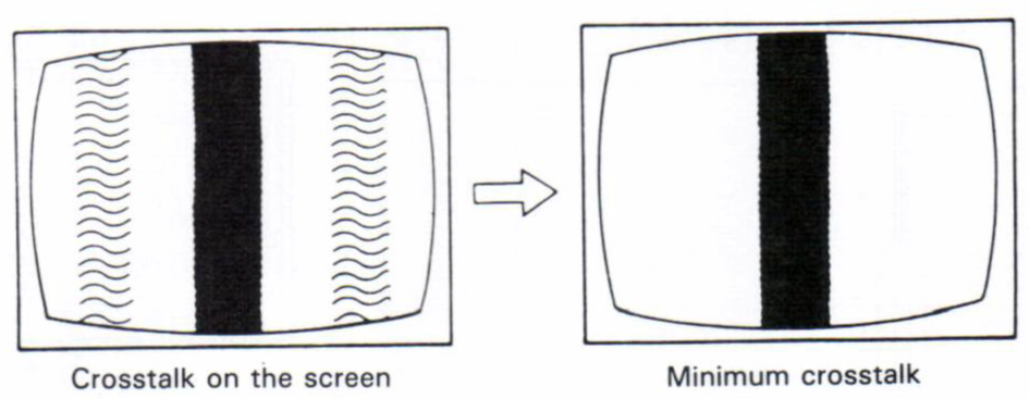
Pick-up tracking and tangential direction inclination adjustment (4)
Purpose
Adjust the angle of the pick-up assembly in the tracking direction so that the laser beam strikes the disc perpendicularly (at a right angle).
Symptoms when incorrectly adjusted
Crosstalk.
Measurement equipment & jigs
- TV monitor
- Philips screwdriver
- Test disc: GGV1069
Measurement equipment connecting points
TV monitor - Connect to the video output terminal of the player.
Player condition
- Service mode
- Tracking servo loop closed - still-frame
- Tilt servo off
- Focus Balance 0
Adjustment points
Tracking direction angle adjustment screw and tangential direction angle adjustment screw in the pick-up assembly:
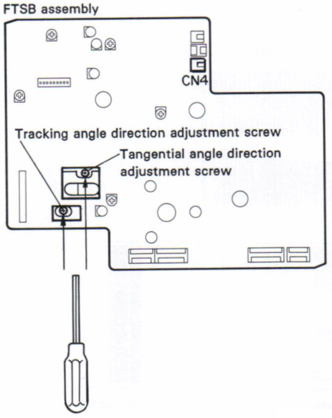
Note: The tracking angle adjustment moves the optics to and from the centre of the disc. The tangential angle moves the optics side-to-side perpendicular from the centre of the disc.
Adjustment procedure
Note: This adjustment should be performed with the unit placed horizontally.
- Play the test disc and search for frame #115.
- Rotate the tracking angle and tangential angle adjustment screws alternately and adjust repeatedly so that the crosstalk occurring on the right and left sides of the TV screen becomes minimum.
Note: As a general rule... If the cross talk is more visible only on one side of the black bar, the main adjustment will be to the tracking angle. If the crosstalk is visible equally on both sides, the tangential angle screw requires adjusting. Move the screws in very small amounts and return the screw back if the tracking fails and the player is unable to continue playing frame #115. You have to be very careful with the screws so you don't 'knock' the slide drive and cause the player to re-track itself.
Note: Other Pioneer service manuals recommend that you clean the screen of the TV used to monitor the player, turn the brightness up and the contrast down to make it easier to see the crosstalk.
Note: If alignment is out the player may refuse to spin up the disc. In cases where the alignment isn't too far out, pressing lightly on the disc-edge over the centre line of the pick-up can be enough to cause the player to start spinning.
Note: If the player is very badly out of alignment it may not be possible to get the player to even still-frame or start playing. As a last resort you can remove the whole deck from the player and try to get the deck straight by looking across the head and adjusting the screws as required. Don't try this until all else fails though!
Adjustment diagrams

Note: Some LCD TVs can blur the picture slightly making it difficult to see the cross talk. Use a CRT monitor for this adjustment if you have access to one. Also, some LCD TV up-scalers are confused by the NTSC still-frame picture and this can cause the image to wobble from side-to-side. If the picture is stable during playback and wobbles during still-frame, use another TV before suspecting calibration issues.
Focus error balance adjustment (5)
Purpose
To set the object lens to its optimum position so that it works optimally with the focus servo while playing a disc.
Symptoms when incorrectly adjusted
Crosstalk.
Measurement equipment & jigs
- TV monitor
- Test disc: GGV1069
- Oscilloscope
Measurement equipment connecting points
- TV monitor - Connect to the video output terminal of the player.
- Oscilloscope: In the FTSB assembly CH1: Between TRKG ERROR (TP1-9) and GND
Player condition
- Service mode
- Tracking servo loop open
- Tilt servo off
- Focus Balance 1
Adjustment points
VR7 in the FTSB assembly
Adjustment procedure
- Play the test disc in the service mode.
- Around the position of frame #1,000, open the tracking servo, set focus balance to '1' and write down the error level (A) at this time.
- Close the tracking servo, set focus balance to '0' and search for frame #115.
- Observe the crosstalk appearing on both the left and right sides of the TV screen and check that the crosstalk is minimum and symmetrical. If crosstalk seems to be in good condition, this adjustment is finished.
- If the crosstalk observed above is not acceptable, re-adjust VR7 in the FTSB assembly to get minimum cross- talk.
- Open the tracking servo again and move to around frame # 1,000 and write down the error level (B) at this time.
- When level difference between A and B is within 30% (B / A >= 0. 7), this adjustment is finished.
- If the level difference is more than 30%, return VR7 so that it becomes within 30%.
- Close the tracking servo again and search for frame # 115 and check that the crosstalk is minimum and symmetrical.
- If the crosstalk seems in good condition, this adjustment is finished. If it is not acceptable, perform item "Pick-up tracking and tangential direction inclination adjustment (4)" again.
Adjustment diagram
Waveforms
Pick-up assembly centering check (6)
Purpose
To check that the centre of the spindle motor is on the track of the laser beam.
Measurement equipment & jigs
- Oscilloscope
- Test disc: GGV1069
Measurement equipment connecting points
- Oscilloscope: On FTSB assembly
- X-Y mode
- CHI (X): Between TP1-9 (TRKG Error) and GND
- CH2 (Y): TP1-4 (TRKG A+C)
Player condition
- Service mode
- Tracking servo loop open
- Tilt servo off
- Focus Balance 1
Adjustment procedure
- With the player set horizontally, play the test disc.
- After moving the pick-up toward inside of the disc using the Step keys, open the tracking servo (if not already open).
- Connect the X-input (CHI) of the oscilloscope to TP1-9 (TRKG ERROR) on FTSB assembly and the Y-input (CH2) to TP1-4 (TRKG A+C). Set the oscilloscope to the X-Y mode, and observe the Lissajous waveform of the TRKG error signal and the TRKG A+C signal
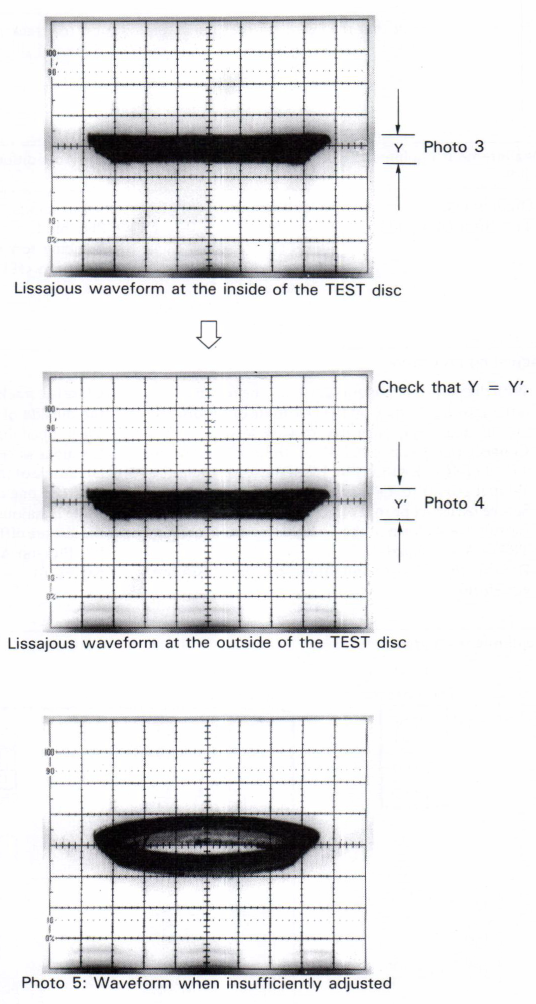
- Record the Y-axis amplitude of the Lissajous waveform.
- Close the tracking servo and move the pick-up toward the outside of the disc using the SCAN FWD keys. Then, open the tracking servo again, and observe the Lissajous waveform. At this time, check that the Y-axis amplitude of the Lissajous waveform is the same as the recorded one in step 4.
If the Lissajous waveforms of the inside and outside of the disc are different in their Y-axis amplitude, perform "Pick-up Assembly Centering Adjustment (7)".
Note: This calibration checks that the level is the same on both the inside and outside of the disc. The waveform should start flat (on the inside), gradually become more oval (towards the centre) and then go flat again (on the outside). There can be some variance in the actual peak-to-peak level of the Y-axis, but it should not be a visible oval on the inside or the outside of the disc.
Waveforms
Oscilloscope range:
- CH1 (X): 0 .2V/div., DC input
- CH2 (Y): 0.2V/div., AC input
- X-Y mode
Pick-up assembly centering adjustment (7)
Purpose
To adjust so centre of the spindle motor comes on the track of the laser beam.
Symptoms when incorrectly adjusted
Track jumping and longer search times.
Measurement equipment & jigs
- Oscilloscope
- Short-shaft hexagonal wrench (2 mm) or L-shaped hexagonal wrench
- Test disc: GGV1069
Measurement equipment connecting points
- Oscilloscope: On FTSB assembly
- X-Y mode
- CH1 (X): Between TP1-9 (TRKG Error) and GND
- CH2 (Y): TP1-4 (TRKG A+C)
Player condition
- Service mode
- Tracking servo loop open
- Tilt servo off
- Focus Balance 1
Adjustment points
Centering adjustment screw in the pick-up assembly:
Adjustment procedure
Note: This adjustment should be performed only when the pick-up assembly is insufficiently adjusted according to "Pick-up assembly centering check (6)". (See above)
- Connect the X-input (CH1) of the oscilloscope to TP1-9 (TRKG ERROR) in FTSB assembly and Y input (CH2) to TP1-4 (TRKG A+ C) respectively.
- Play the test disc and search for frame #20,000 using the SCAN FWD key to move the pick-up towards the outside of the disc.
- Open the tracking servo and observe the Lissajous waveform of the TRKG error signal and the TRKG A+C signal.
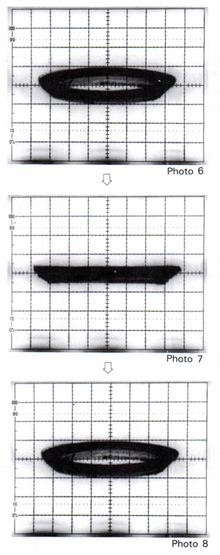
- Fine adjust the centering screw so that the Y-axis amplitude of the Lissajous waveform becomes minimum. (Photo 7)
- Move the pick-up toward the inside of the disc by pressing the SCAN REV key.
- Observe the Lissajous waveform and record its Y-axis amplitude.
- Move the pick-up toward outside again and rotate the centering adjustment screw clockwise by 45° with the hexagonal wrench.
Then rotate the centering adjustment screw slowly so that the Y-axis amplitude of the Lissajous waveform decreases.
After the Y-axis amplitude of the Lissajous waveform becomes minimum, rotate the hexagonal wrench further in the same direction until the Y-axis amplitude of the Lissajous waveform becomes the same level as the recorded one in step 6. (Photo 6 - 8) - Move the pick-up toward the outside of the disc using the SCAN FWD key.
- Repeat the operation in steps 3, 4 and 5.
- Open the TRKG servo again to observe the Lissajous waveform and check that the Y-axis amplitude is minimum.
If the Lissajous waveform is expanded in the Y-axis direction, repeat the operation in steps 7, 8, 9, and 10.
Note: You basically have to go back and forth with this adjustment gradually moving the adjustment until the waveform's Y-axis height is as equal as possible at both ends of the disc. The Y-axis height will always be lower in the centre of the disc.
Waveforms
Oscilloscope range:
- X: 0 .2V/div., DC input
- Y: 0.2V/div., AC input
- X-Y mode
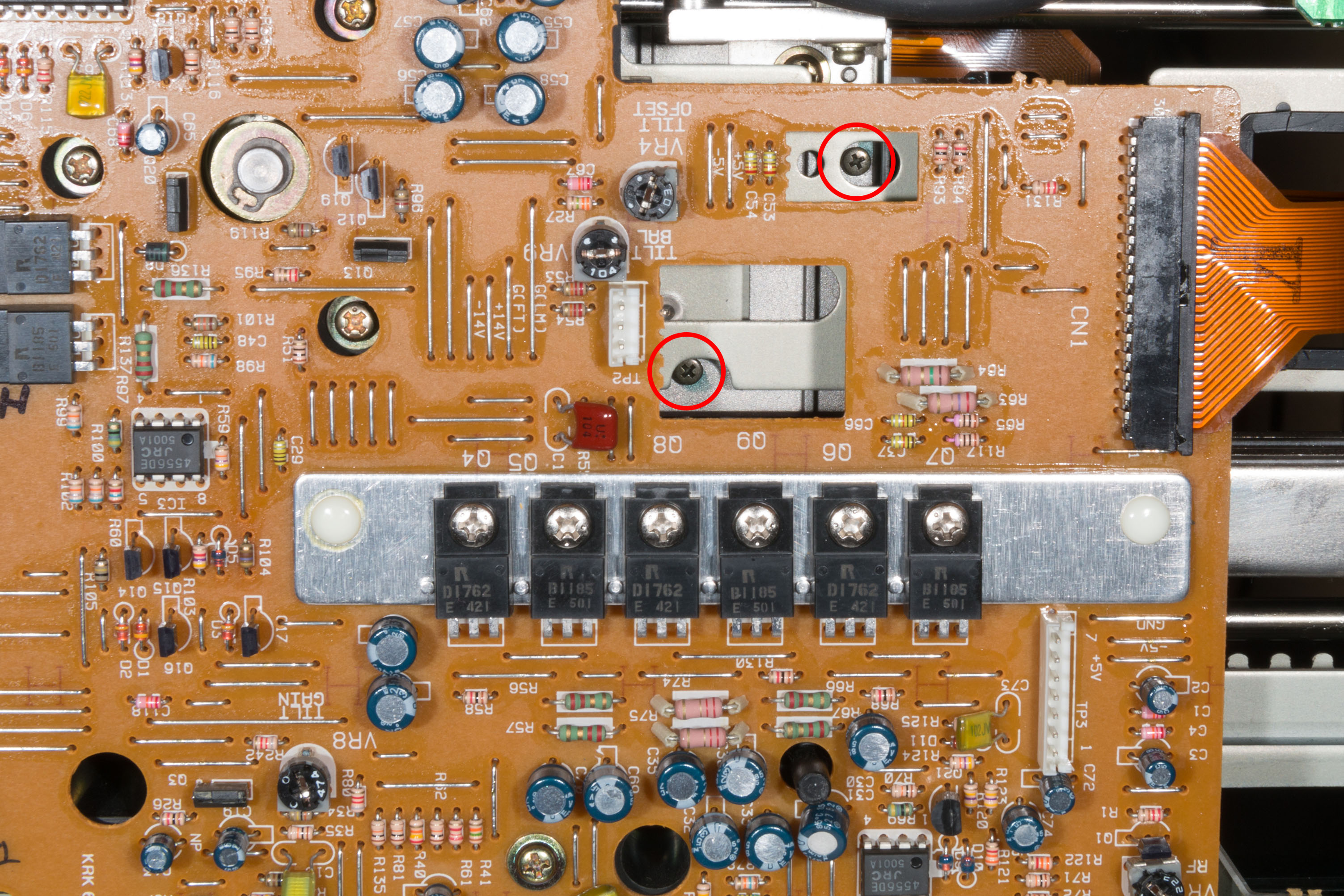
Tilt sensor inclination adjustment (8)
Purpose
To set the electrical offset of the tilt servo to 0V by adjusting the inclination of the tilt sensor.
Symptoms when incorrectly adjusted
Crosstalk
Measurement equipment & jigs
- Oscilloscope
- Test disc: GGV1069
- Philips screwdriver
- Monitor TV
Measurement equipment connecting points
Oscilloscope: On FTSB assembly - CH1: Between TP1-8 (TILT ERROR) and GND
Player condition
- Service mode
- Tracking servo loop open
- Tilt servo off
- Focus Balance 1
Adjustment points
Tilt sensor inclination adjustment screw in the pick-up assembly
Adjustment procedure
Note: This adjustment should be performed with the unit placed horizontally.
This adjustment should be performed in the range of frames 2000 - 10000 so the sensor output is not influenced by the mirror surface at the inside of the disc and external light at the edges of the disc.
- Play the test disc and search for a position around frame #5000.
- Connect the oscilloscope to TP1-8 in the FTSB assembly and observe the DC voltage of the tilt error signal (i.e. in relation to GND).
- Lock the pick-up mechanism in place using the service remote
- Insert the small Philips screwdriver with a long shaft from the rear panel of the player and adjust the tilt sensor inclination adjustment screw so that the DC voltage of the tilt error signal becomes 0V ±20mV.
- Set "TILT SERVO ON" using the remote control.
- Search for frame #115 and check that crosstalk at the left and right sides of the TV screen is minimum and symmetrical.
Note: It is almost impossible to get the player within 20mV of 0V with this adjustment. Ambient light, the screwdriver, pressure on the mechanism and the slightest movement of the pick-up causes the voltage to swing rapidly. Since the pick-up can move slightly even when locked it's necessary to attempt the calibration several times to get within the correct range. In practice a variation within 100mV works perfect well. Getting the screwdriver in the right place also takes some practice - be patient!
Note 2: It is possible that VR4 can be used to fine tune this setting (although this is missing from the original service manual). Set it to the centre position then perform the mechanical calibration before adjusting VR4.
Waveforms
Grating fine adjustment and tracking balance check (9)
Purpose
To fine adjust the grating so that the two laser beams for TRKG (tracking) servo are emitted at the optimum track positions of the disc. Set the DC off-set voltage to 0V of TRKG Servo.
Symptoms when incorrectly adjusted
Track jumping.
Measurement equipment & jigs
- Oscilloscope
- Test disc: GGV1069
- Flat bladed screwdriver
Measurement equipment connecting points
- Oscilloscope: On the FTSB assembly
- X-Y mode
- CH1 (X): Between TP1-9 (TRKG ERROR) and GND
- CH2 (Y): TP1-4 (TRKG A+C)
Player condition
- Service mode
- Tracking servo loop open
- Tilt servo off
- Focus Balance 1
Adjustment points
Grating adjustment screw in the pick-up assembly
Adjustment procedure
- Play the test disc and search for frame #16,000, then open the TRKG servo.
- Connect the X-input (CHI) of the oscilloscope to TP1-9 (TRKG ERROR) of the FTSB assembly and Y-input (CH2) to TP1-4 (TRKG A+C) respectively. Set the oscilloscope to the X-Y mode and observe the Lissajous waveform of the TRKG error signal and TRKG A+C signal.
- Insert the flat-bladed small screwdriver into the grating adjustment hole, and fine adjust the grating so that the Y-axis dimension of the Lissajous waveform becomes minimum.
At this time, if the grating is rotated excessively and the optimum point becomes unclear, perform "Grating Temporary Adjustment (2)" again. - Select the X-input (CH1) of the oscilloscope and check that the positive (A) and negative (B) amplitudes of the TRKG error signal are equal. (Photo 10)
If the sizes of the positive and negative amplitude are different, perform "Pick-up Tracking and Tangential Direction Inclination Adjustment (4)" again. - Close the tracking servo loop and check that the picture on the TV screen is normal.
Note: It's important that, when performing this calibration, you don't adjust the grating too much and end up on a different null point (on-track position) from the initial one. The adjustment is very small. You will clearly see in step 5 if you have performed this incorrectly as the picture will be very poor.
Waveforms
Oscilloscope range:
- Grating adjustment
- CH1 (X): 0.5V/div., DC input
- CH2 (Y): 0.5V/div., DC input
- X-Y mode
- TRKG balance adjustment
- CH1: 1V /div., 5mS/div.
RF gain adjustment (10)
Purpose
To set the amplitude of the RF signal to the optimum value.
Symptoms when incorrectly adjusted
Drop-outs occur frequently.
Measurement equipment & jigs
- Oscilloscope
- Test disc: GGV1069
Measurement equipment connecting points
Oscilloscope: On the FTSB assembly - CH1: Between TP1-1 (RF) and GND
Player condition
- Service mode
- Tracking servo loop closed - still frame
- Tilt servo off
- Focus Balance 1
Adjustment points
VR1 in the FTSB assembly
Adjustment procedure
- Play the test disc and search for frame # 15,000.
- Connect the oscilloscope to TP1-1 in the FTSB assembly to observe the RF signal.
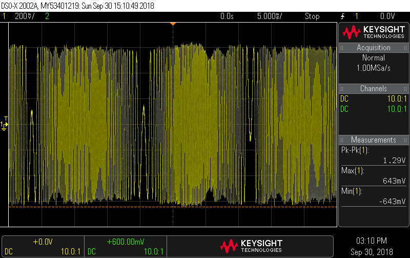
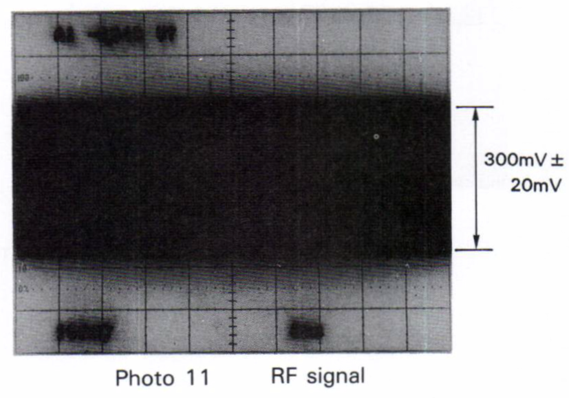
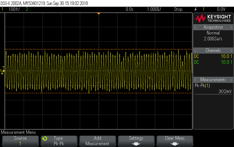
- Adjust VR1 in the PREB assembly so that the amplitude of the RF signal becomes 300mV ±20mV. (Photo 11)
Note: If it's not possible to get the RF level to 300mV peak-to-peak then the signal from the pick-up is too weak. Most likely this is caused by an incorrect tangential angle and you will need to repeat the calibration procedure from the beginning (making sure the peak-to-peak of the radial error signal is at the correct amplitude before proceeding).
Waveforms
Oscilloscope range: AC 100mV/div., 2mS/div.
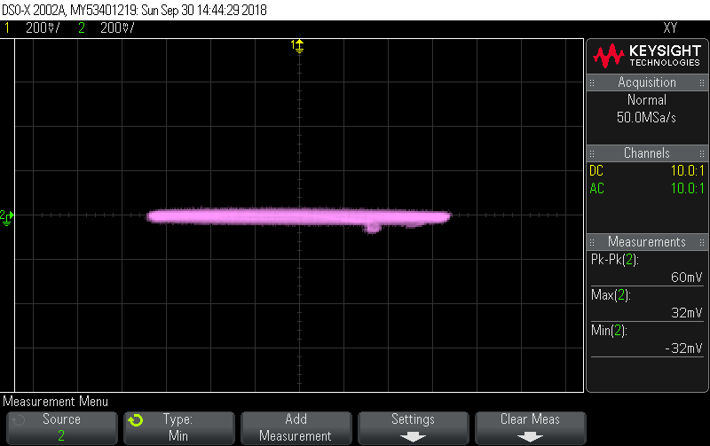
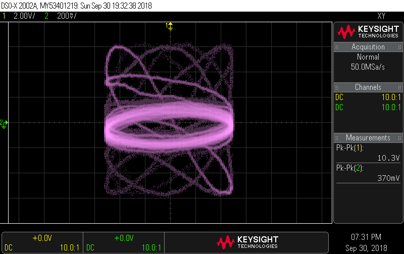
Focus servo loop gain adjustment (11)
Purpose
To set the loop gain of the FOCS (focus) servo to the optimum value.
Symptoms when incorrectly adjusted
Play ability gets worse as the player moves through a disc.
Measurement equipment & jigs
- Oscilloscope
- Test disc: GGV1069
- AF oscillator (i.e. a frequency generator capable of producing a sine-wave at the required frequency)
- Resistor (100Kohm)
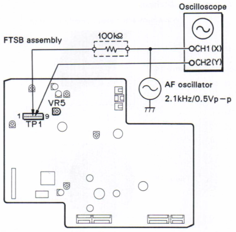
Measurement equipment connecting points
- Oscilloscope: On FTSB assembly:
- CH1 (X): Between TP1-5 (FOCS ERR IN) with 100Kohms and GND
- CH2 (Y): TP1-6 (FOCS ERR OUT)
Player condition
- Service mode
- Tracking servo loop closed - still-frame
- Tilt servo off
- Focus Balance 1
Adjustment points
VR5 in the FTSB assembly
Adjustment procedure
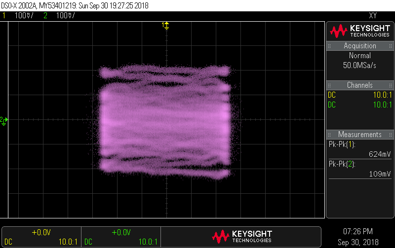
- Play the test disc and search for frame # 15,000.
- Connect the X and Y terminals of the oscilloscope as shown above and observe the Lissajous waveform.
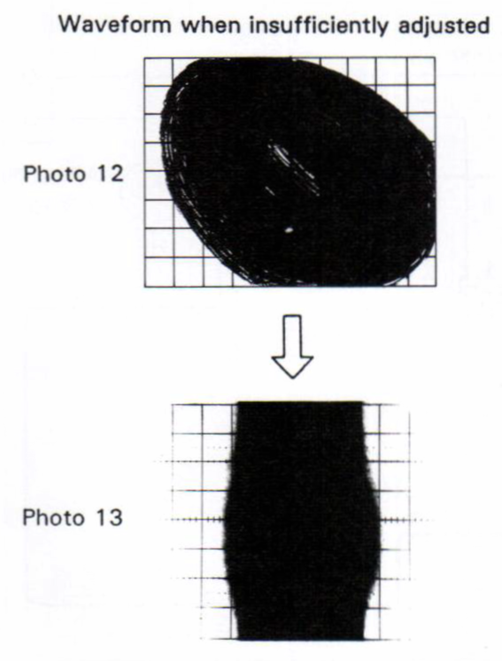
- Adjust VR5 so that the Lissajous waveform shown in Photo 13 appears. Photo 12 shows a waveform when the adjustment is incorrect.
Note: This adjustment procedure (copied from the service manual) didn't appear to work when tested. The simplest method seems to play the test disc from frame 23,401 (tracking servo closed - playback) and observe the picture. If lines appear or the playback is stuttering adjust VR5 upwards until the picture is stable.
Note: When adjusting VR5 listen carefully to the focus mechanism as it's possible to hear the focus 'hunting' if VR5 is adjusted too far.
Waveforms
Oscilloscope range:
- X-Y mode
- X: 100mV/div. DC input
- Y: 20mV/div. DC input
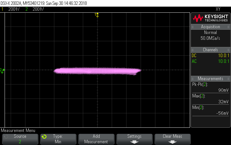
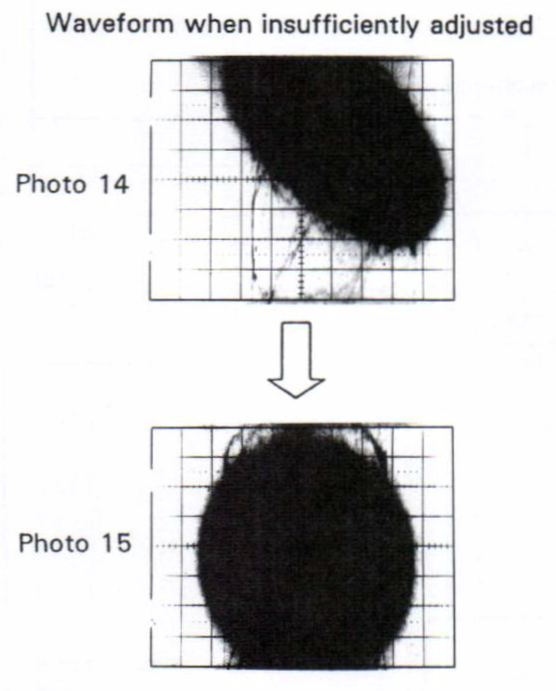
Tracking servo loop gain adjustment (12)
Purpose
To set the loop gain of the TRKG (tracking) servo to the optimum value.
Symptoms when incorrectly adjusted
Play ability grow worse.
Measurement equipment & jigs
- Oscilloscope
- Test disc: GGV1069
- AF oscillator (i.e. a frequency generator capable of producing a sine-wave at the required frequency)
- Resistor (100Kohm)
Measurement equipment connecting points
- Oscilloscope: On FTSB assembly :
- X-Y mode
- CH1 (X): Between TP1-7 (TRKG ERR IN) with 100Kohm and GND
- CH2 (Y): TP1-9 (TRKG ERR OUT)
Player condition
- Service mode
- Tracking servo loop closed - still-frame
- Tilt servo off
- Focus Balance 1
Adjustment points
VR3 in the FTSB assembly
Adjustment procedure
- Play the test disc and search for frame # 15,000.
- Connect the X and Y terminals of the oscilloscope as shown above and observe the Lissajous waveform.
- Adjust VR3 so that the Lissajous waveform as shown in Photo 15 appears. Photo 14 shows a waveform when the adjustment is incorrect.
Note: This adjustment procedure (copied from the service manual) didn't appear to work when tested. Correctly calibration technique is not known. However, altering the adjustment to make the oval's axis horizontal seems to yield the correct results.
Waveforms
Oscilloscope range:
- X-Y mode
- X: 0.2mV/div. DC input
- Y: 10mV/div. DC input
Checking the tilt operation (13)
Adjustment procedure
- Connect the TILT connector. Turn TILT OFF by using the remote-control unit.
- Move the tilt motor using the [SKIP FWD] or [SKIP RWD] key and change TILT ERR display to “0D” or “13” from "10".
- Confirm that TILT ERR converges to "10 tolerance (0F to 11)" when TILT SERVO is turned on by the [SPEED UP] key.